System and layout method for airframe three-section involution and intersection hole machining

An aircraft fuselage and intersection hole technology, which is applied in aircraft assembly, aircraft parts, ground devices, etc., can solve the problems of low degree of automation, manufacturing error positioning and deformation of aircraft parts, and deformation and rebound of aircraft parts, so as to reduce assembly costs. , the effect of high degree of flexibility and high degree of automation

Inactive Publication Date: 2013-06-26
ZHEJIANG UNIV
View PDF6 Cites 12 Cited by
  • Summary
  • Abstract
  • Description
  • Claims
  • Application Information

AI Technical Summary

Problems solved by technology

The traditional assembly method uses a large number of jigs to locate and fix aircraft parts. Due to the manufacturing errors of the jigs used, and the manufacturing errors of the aircraft parts to be assembled, as well as the positioning and deformation errors in the early stage, resulting in The assembled joints cannot be accurately matched with the corresponding positioning joints on the frame, and the coordination of the butt joint assembly is poor
In this case, the traditional assembly method is difficult to take effective adjustment measures, often need to use the method of forced positioning
Forced positioning will cause assembly stress and deformation during the assembly process. When the assembly is completed and the aircraft components are separated from the frame, the aircraft components may deform and rebound, which will affect the shape accuracy of the aircraft.
Moreover, in the traditional assembly method, the attitude adjustment and docking of the components, as well as drilling and riveting, etc. are all done by manual operations, the degree of automation is low, and the assembly quality is unstable.

Method used


Image

  • System and layout method for airframe three-section involution and intersection hole machining
  • System and layout method for airframe three-section involution and intersection hole machining

Examples


Embodiment Construction

[0023] The present invention will be further described below in conjunction with accompanying drawing.

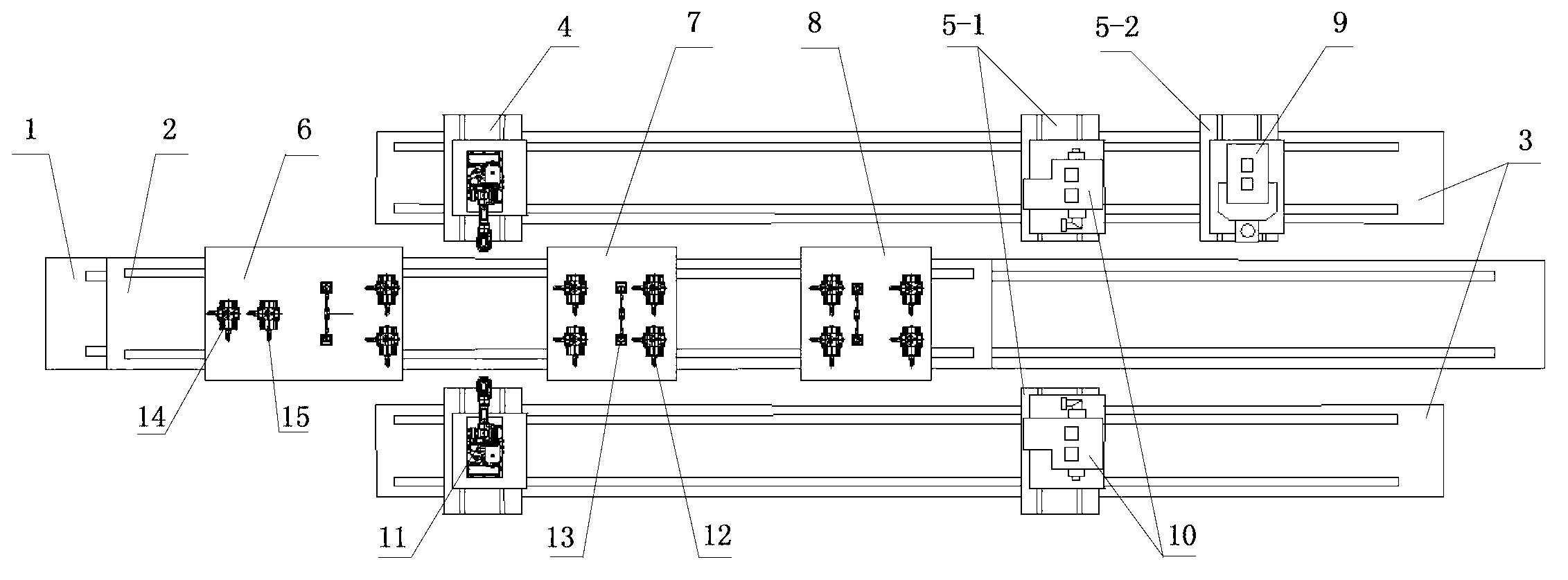
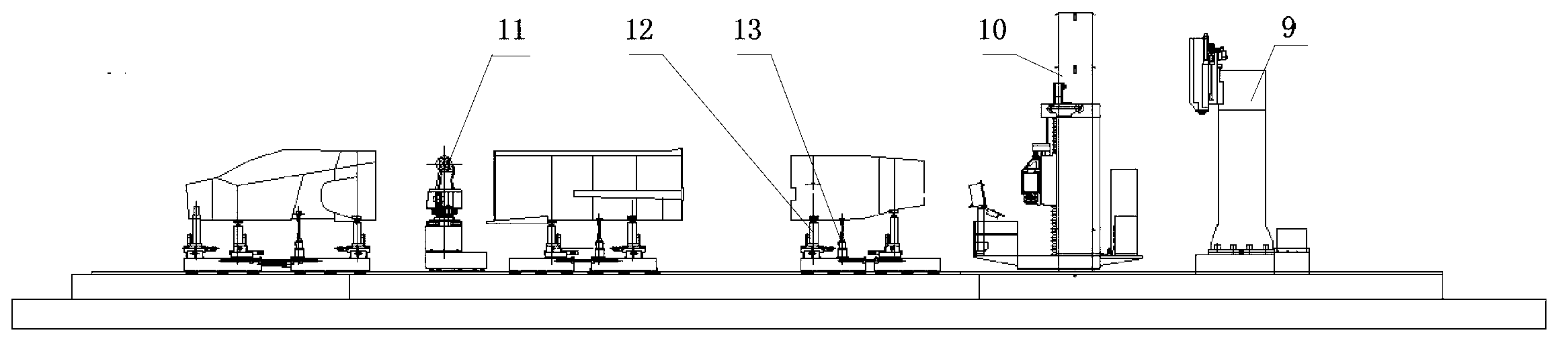
[0024] Such as figure 1 , figure 2 As shown in the figure, a system for three-section alignment and intersection hole processing of an aircraft fuselage includes a fuselage posture adjustment alignment area and a fuselage processing area, specifically including a basic platform 1, a 25-meter mobile platform 2, an auxiliary platform 3, and a robot Mobile platform 4, machining center mobile platform 5, front fuselage attitude adjustment platform 6, middle fuselage attitude adjustment platform 7, rear fuselage attitude adjustment platform 8, one vertical machining center 9, two horizontal machining centers 10 and Two industrial robots 11; auxiliary platforms 3 are symmetrically arranged on the left and right sides of the basic platform 1;

[0025] The attitude adjustment area of ​​the fuselage includes the basic platform 1, the 25-meter mobile platform 2, the front fuselage...


PUM


Abstract

The invention discloses a system and a layout method for airframe three-section involution and intersection hole machining. The system comprises an airframe gesture adjusting involution area and an airframe machining area and particularly comprises a foundation platform, 25-meter moving platform, auxiliary platforms, a robot moving platform, a machining center moving platform, a front airframe gesture adjusting platform, a middle airframe gesture adjusting platform, a rear airframe gesture adjusting platform, an upright type machining center, two horizontal type machining centers and two industrial robots. The left side and the right side of the foundation platform are respectively and symmetrically provided with one auxiliary platform. The layout method comprises the following steps of 1, each airframe location; 2, three-section airframe involution; 3, airframe intersection hole face machining; and 4, system part installation. The system for the airframe three-section involution and the intersection hole machining is high in flexible degree, compact in layout, high in assembly efficiency, high in automatic degree and capable of greatly improving gesture adjusting involution accuracy and machining accuracy.

Description

technical field [0001] The invention belongs to the technical field of aircraft digital assembly, and relates to a system and a layout method for combining three segments of an aircraft fuselage and processing intersection holes. Background technique [0002] Aircraft fuselage alignment and intersection hole processing is an extremely important part of the aircraft manufacturing process. Due to the complex shape of the product, the large number of parts and connectors, and the complex coordination parts, the labor volume accounts for about half or more of the total labor volume of aircraft manufacturing, which largely determines the final quality, manufacturing cost and cycle of the aircraft. The key and core link of aircraft manufacturing. [0003] In recent years, my country's aviation manufacturing enterprises have introduced a large number of world-class CNC machine tools, the CNC machining capabilities of aircraft parts have been strengthened, and the processing qualit...

Claims


Application Information

Patent Timeline
Patent Type & Authority Applications(China)
IPC IPC(8): B64F5/00B64F5/10
Inventor 刘刚刘春张恒王亚飞章明柯映林李松张雷
Owner ZHEJIANG UNIV
Why Eureka
Try Eureka