Hydraulic energy-saving system

An energy-saving system and hydraulic technology, which can be used in fluid pressure actuation system components, fluid pressure actuation devices, mechanical equipment, etc., and can solve problems such as energy waste, energy loss, and system pressure loss.

Active Publication Date: 2013-06-26
NANJING UNIV OF TECH
View PDF9 Cites 39 Cited by
  • Summary
  • Abstract
  • Description
  • Claims
  • Application Information

AI Technical Summary

Problems solved by technology

[0003] In traditional hydraulic systems, there is a large amount of energy loss
Among them, in the oil return line of the system, a large amount of hydraulic oil flows back to the oil tank, resulting in a waste of energy
Secondly, in the hydraulic system, it is often accompanied by hydraulic shock, causing the system pressure to be too high, resulting in overflow. At this time, a large amount of hydraulic oil will flow back into the oil tank through the overflow valve, resulting in pressure loss in the system.

Method used


Image

  • Hydraulic energy-saving system
  • Hydraulic energy-saving system
  • Hydraulic energy-saving system

Examples


Embodiment

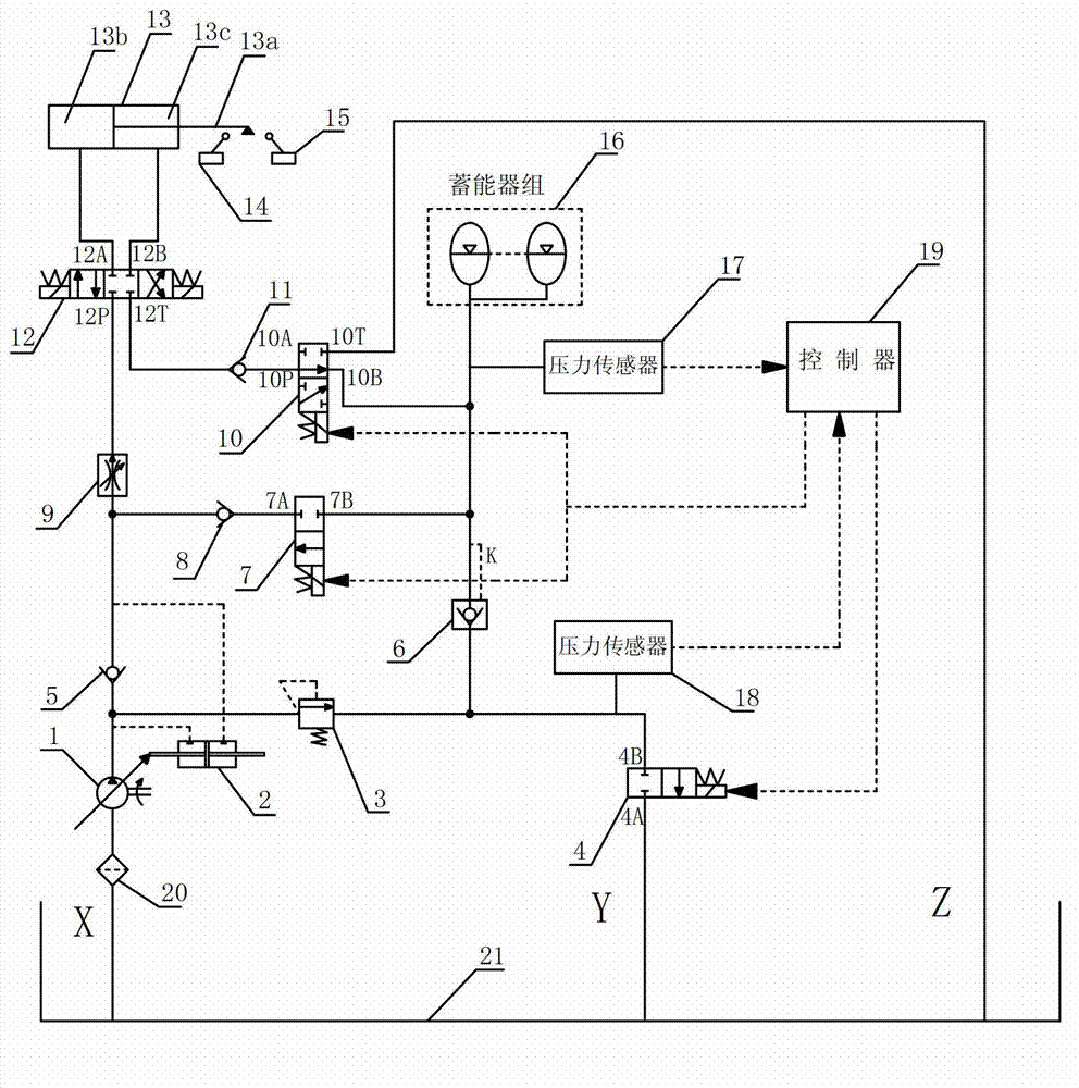
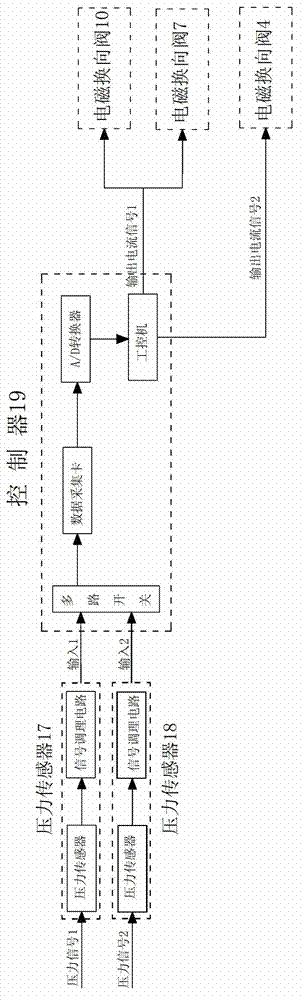
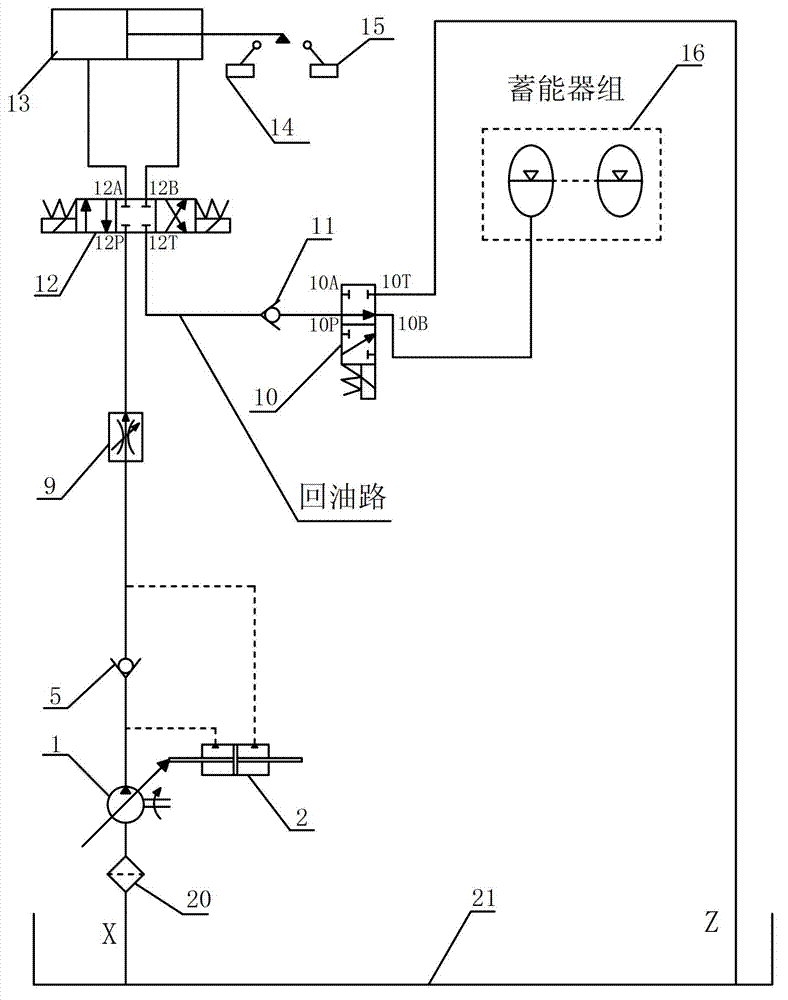
[0027] Such as figure 1 with figure 2 As shown, this embodiment provides a hydraulic energy-saving system, including: variable pump 1, variable oil cylinder 2, overflow valve 3, electromagnetic reversing valve 4, one-way valve 5, hydraulic control one-way valve 6, electromagnetic reversing Valve 7, check valve 8, speed control valve 9, solenoid reversing valve 10, check valve 11, solenoid reversing valve 12, hydraulic cylinder 13, travel switch 14, travel switch 15, bladder accumulator 16, pressure Sensor 17, pressure sensor 18, controller 19, filter 20, hydraulic oil tank 21. Among them, the pressure sensor 17 and the pressure sensor 18 are respectively integrated with their own signal conditioning circuits; in the controller 19 there are multiple switches, data acquisition cards, A / D converters, and industrial computers.

[0028] The connection method of this embodiment is: the oil outlet X of the hydraulic oil tank 21 is connected to the oil inlet of the variable pump 1 throu...


PUM


Abstract

The invention discloses a hydraulic energy-saving system which includes a hydraulic oil tank, a variable pump, a speed control valve, a first electromagnetic directional valve, a hydraulic cylinder, a first travel switch, a second travel switch, a second electromagnetic directional valve, a third electromagnetic directional valve, a fourth electromagnetic directional valve and an energy accumulator. When the hydraulic oil tank adds oil to a rodless cavity of a hydraulic cylinder, the oil in a rod cavity of the hydraulic cylinder flows into the energy accumulator through a pipeline. In a restoration process of the hydraulic cylinder, the energy accumulator adds the oil into the rod cavity of the hydraulic cylinder through the pipeline. The hydraulic energy-saving system solves the loss problem of hydraulic oil in an oil return pipeline and an overflow pipeline in a traditional hydraulic system; the hydraulic oil in the oil return pipeline and the overflow pipeline is recycled through the hydraulic energy-saving system. The recycled hydraulic oil is reutilized in a main oil channel so that the purpose of energy-conservation is achieved.

Description

Technical field [0001] The invention relates to the field of hydraulics, in particular to a hydraulic energy-saving system. Background technique [0002] With the continuous development of human society and the continuous improvement of the level of industrialization, energy issues have become an urgent concern in today's society. Hydraulic systems are widely used in machinery industry, such as machine tool industry, automobile industry, construction machinery and other heavy machinery industries. [0003] In traditional hydraulic systems, there is a lot of energy loss. Among them, in the oil return pipeline of the system, a large amount of hydraulic oil flows back to the oil tank, causing a waste of energy. Secondly, in the hydraulic system, there is often a hydraulic shock, which causes the system pressure to be too high, resulting in overflow. At this time, a large amount of hydraulic oil will flow back into the oil tank through the overflow valve, causing the pressure loss of...

Claims


Application Information

Patent Timeline
Patent Type & Authority Applications(China)
IPC IPC(8): F15B1/02F15B21/04
Inventor 殷晨波高俊庭叶仪袁峰峰周玲君
Owner NANJING UNIV OF TECH
Why Eureka
Try Eureka