
Hydraulic Oil Filtration System and Hydraulic Excavator

A hydraulic oil filtration and hydraulic oil tank technology, which is applied to fluid pressure actuation system components, earth movers/shovels, mechanical equipment, etc., can solve the problem of low efficiency of bypass filters, large back pressure, and low oil return pressure And other issues

Active Publication Date: 2016-02-17
ZOOMLION HEAVY IND CO LTD
View PDF9 Cites 0 Cited by
  • Summary
  • Abstract
  • Description
  • Claims
  • Application Information

AI Technical Summary

Problems solved by technology

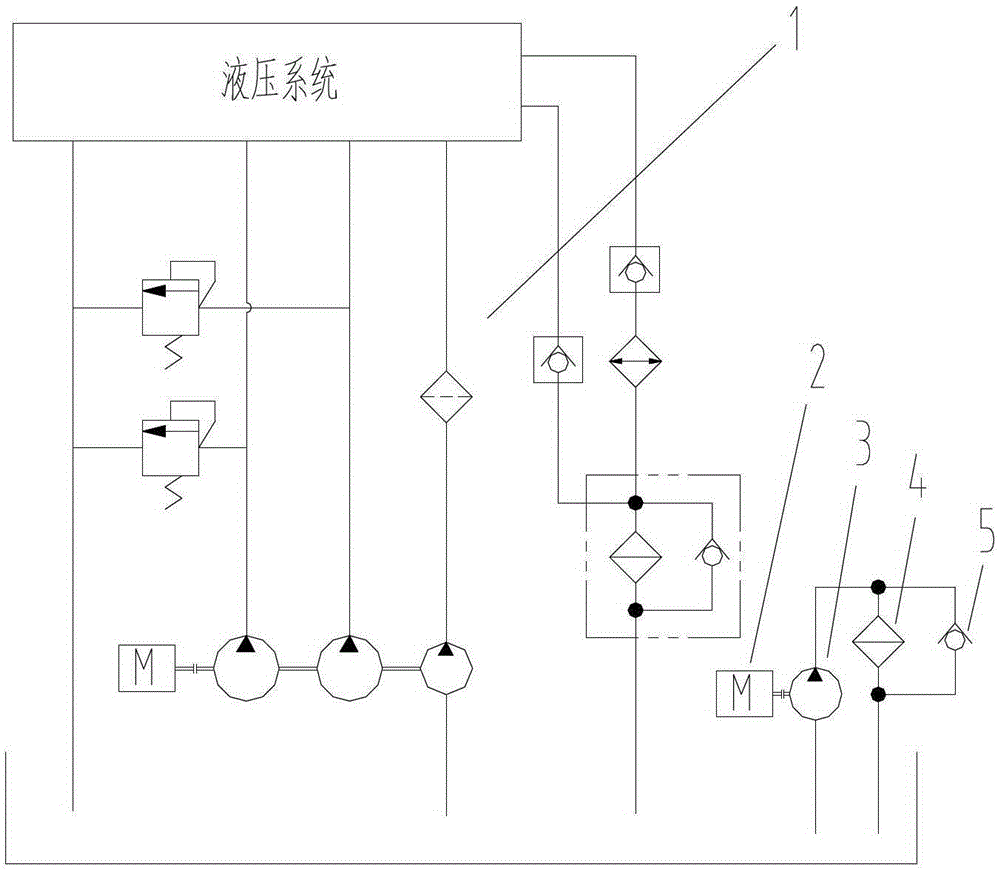
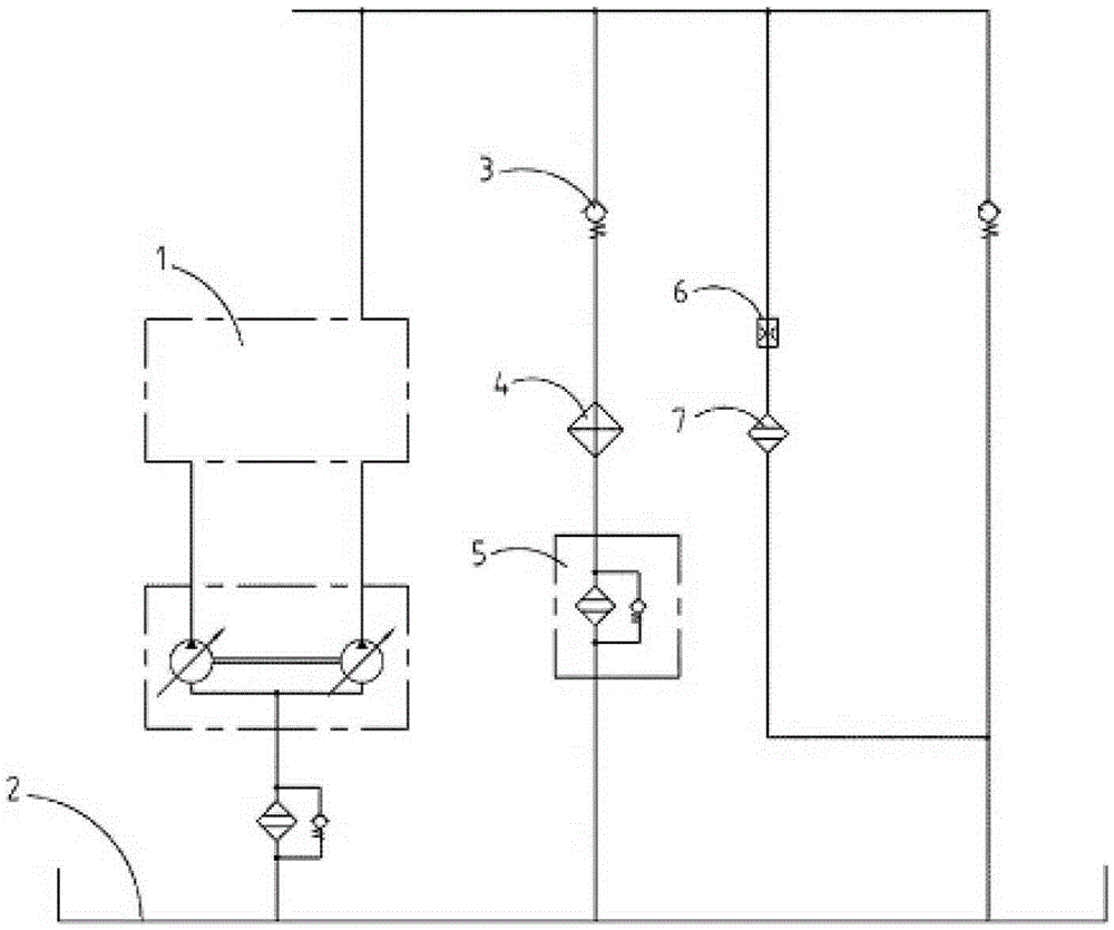
This method can reduce costs, has no noise, and can meet the installation requirements of general medium and large excavators. The disadvantage is that due to the parallel connection method, the hydraulic oil is introduced into the bypass filter for filtering by relying on the system oil return pressure. Small and unstable, and the bypass filter has a high filtration precision and a large back pressure, so the flow through the bypass filter is small or even zero during normal use, so that the efficiency of the bypass filter is very low

Method used


Image

  • Hydraulic Oil Filtration System and Hydraulic Excavator
  • Hydraulic Oil Filtration System and Hydraulic Excavator
  • Hydraulic Oil Filtration System and Hydraulic Excavator

Examples


Embodiment Construction

[0030] Specific embodiments of the present invention will be described in detail below in conjunction with the accompanying drawings. It should be understood that the specific embodiments described here are only used to illustrate and explain the present invention, and are not intended to limit the present invention.

[0031] In the present invention, unless stated otherwise, the used orientation words such as "up and down" are usually for the direction shown in the drawings or for the vertical, vertical or gravity direction Words used to describe the mutual positional relationship of each component. The orientation words "left and right" are usually for the horizontal direction shown in the drawings.

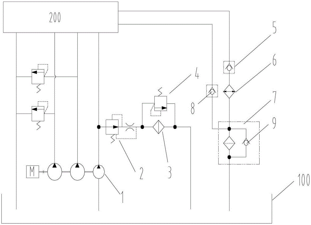
[0032] Such as image 3 As shown, the present invention provides a hydraulic oil filtering system. The hydraulic oil filtering system includes a bypass filter oil circuit provided with a bypass filter 3 and a pilot control system for pilot control of the hydraulic working dev...


PUM


Abstract

The invention discloses a hydraulic oil filtration system and a hydraulic shovel. The hydraulic oil filtration system comprises a pilot control system and a bypass filtration oil way, wherein the pilot control system is used for guiding and controlling a hydraulic working device (200), the bypass filtration oil way is provided with a bypass filter (3), a pilot pump (1) is placed inside the pilot control system, an oil suction of the pilot pump (1) is connected with a hydraulic oil tank (100), one end of the bypass filtration oil way is connected with the hydraulic oil tank (100), and the other end of bypass oil way is connected on a pilot control oil way between the pilot pump (1) and the hydraulic working device (200). Due to the fact that the bypass filtration oil way is provided with the bypass filter and is connected on the pilot control oil way and the hydraulic oil tank, high-precision and high-efficiency filtration is carried out on hydraulic oil by utilizing of a flow rate and oil pressure of the hydraulic oil on the pilot control oil way, working efficiency is improved, and the structure is simple and stable.

Description

technical field [0001] The invention belongs to the field of hydraulic excavators, and in particular relates to a hydraulic oil filtering system of a hydraulic excavator. Background technique [0002] In the hydraulic system of excavators, the failures caused by hydraulic oil pollution account for the majority. In order to control the cleanliness of hydraulic oil, in addition to adopting a conventional filter device, a bypass filter is installed to filter the hydraulic oil with higher precision, which can reduce the failure rate of the hydraulic system and improve the reliability of the whole machine. [0003] At present, there are two ways to use the bypass filter on the excavator. One method is that the bypass filter has its own power system (such as a motor), such as figure 1 As shown, the bypass filter circuit is composed of the motor 2, the pump 3, the bypass filter 4 and the one-way valve 5, so that the hydraulic oil in the hydraulic oil tank can be independently circ...

Claims


Application Information

Patent Timeline
Patent Type & Authority Patents(China)
IPC IPC(8): F15B21/04E02F9/22
Inventor 何骞张明珍白晶黄志强
Owner ZOOMLION HEAVY IND CO LTD
Learn More