
Photoelectric converter

A technology of photoelectric converters and optical fibers, which is applied to the coupling of optical waveguides and other directions, can solve the problems of complex manufacturing and high cost of the first and second optical transmission elements

Inactive Publication Date: 2013-06-26
HONG FU JIN PRECISION IND (SHENZHEN) CO LTD +1
View PDF6 Cites 2 Cited by
  • Summary
  • Abstract
  • Description
  • Claims
  • Application Information

AI Technical Summary

Problems solved by technology

However, in order to accurately couple the optical fiber and the lens, the matching dimensions of the first light transmission element and the second light transmission element must be very precise, making the manufacture of the first and second light transmission elements more complicated and costly

Method used


Image

  • Photoelectric converter
  • Photoelectric converter
  • Photoelectric converter

Examples


Embodiment Construction

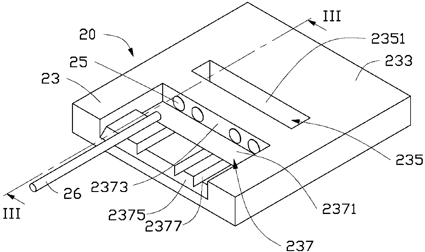
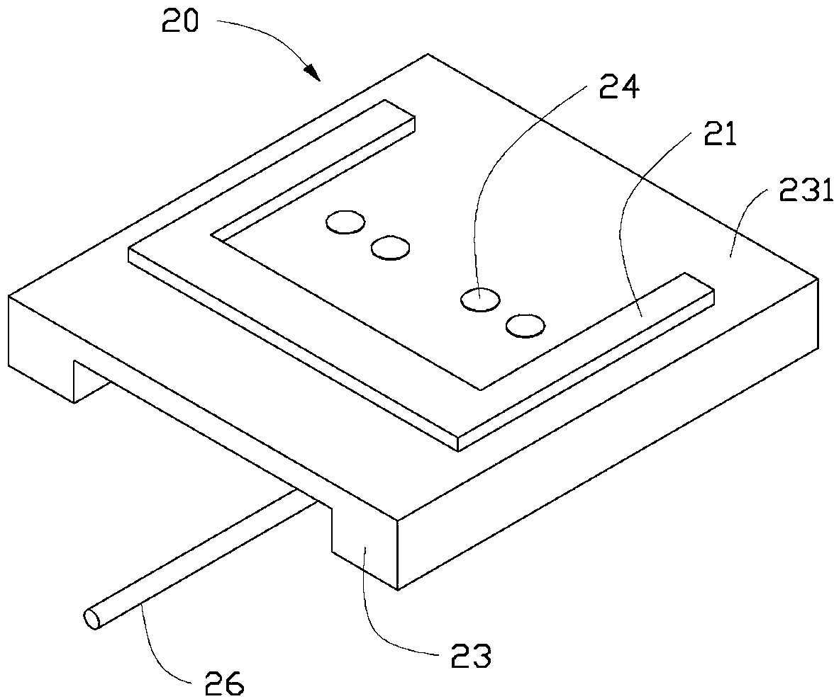
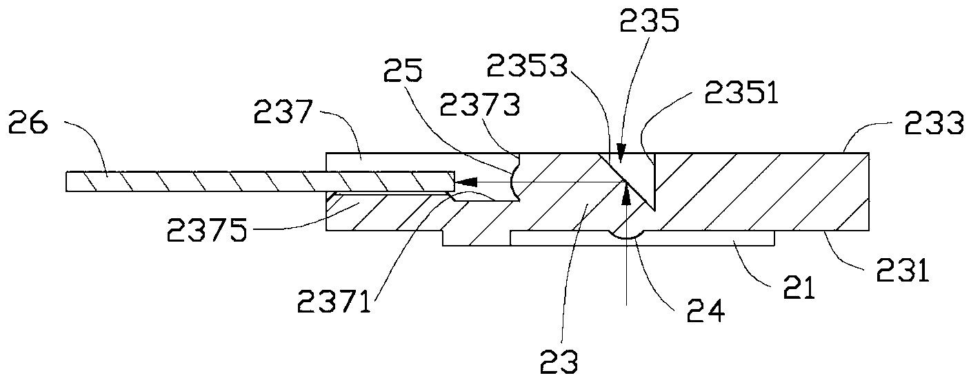
[0013] see figure 1 and figure 2 , the photoelectric converter 20 according to the embodiment of the present invention includes a support plate 21 , a light transmission body 23 , a plurality of first lenses 24 , a plurality of second lenses 25 and a plurality of optical fibers 26 . A plurality of first lenses 24 and a plurality of second lenses 25 are embedded on the light transmission body 23 , and a plurality of optical fibers 26 are inserted in the light transmission body 23 . The support plate 21 is disposed on the bottom of the light transmission body 23 to support the light transmission body 23 above the laser diode (not shown), so that the light transmission body 23 receives and transmits the optical signal emitted by the laser diode. The photoelectric converter 20 is used to transmit and convert optical signals, and it includes various functional modules for realizing various corresponding functions, such as laser diodes for converting electrical signals into optica...


PUM


Abstract

A photoelectric converter comprises a supporting plate, a light transmission main body, a plurality of first lenses, a plurality of second lenses and a plurality of optical fibers arranged on the light transmission main body. The light transmission main body comprises a first surface and a second surface opposite to the first surface. The plurality of first lenses are convexly arranged on the first surface, an optical fiber installation groove is arranged on the second surface and comprises a side surface, and the plurality of second lenses are convexly arranged on the side surface. The optical axes of the first lenses and the optical axes of the corresponding second lenses are located on the same plane, and the plurality of optical fibers are arranged in the optical fiber installation groove. The photoelectric converter can achieve accurate coupling of the optical fibers and the second lenses simply by arranging the optical fibers into the optical fiber installation groove, and is simple in structure and low in manufacture cost.

Description

technical field [0001] The invention relates to the field of photoelectric conversion, in particular to a photoelectric converter. Background technique [0002] A general photoelectric converter includes a laser diode (Laser Diode), a first light transmission element, a second light transmission element coupled with the first light transmission element, and a photodiode (Photo Diode). After the laser diode emits an optical signal, the optical signal enters the first optical transmission element, is transmitted through the second optical transmission element, and finally enters the photodiode. The optical signal is converted into an electrical signal by the photodiode, thereby achieving the purpose of photoelectric conversion. [0003] The first light transmission element and the second light transmission element are generally coupled through a lens and an optical fiber, the lens is mounted on the first light transmission element, and the optical fiber is mounted on the secon...

Claims


Application Information

Patent Timeline
IPC IPC(8): G02B6/42
Inventor 林奕村
Owner HONG FU JIN PRECISION IND (SHENZHEN) CO LTD
Learn More