Lubricant valve for oil pumps of internal combustion engines

A technology for lubricants and internal combustion engines, which is used in the pressure lubrication of lubricating pumps, controlling the pressure of lubricants, liquid fuel engines, etc., and can solve the problems of valve piston stuck, unsuitable, high manufacturing cost, etc.

Inactive Publication Date: 2013-06-26
NIDEC GPM GMBH
View PDF12 Cites 7 Cited by
  • Summary
  • Abstract
  • Description
  • Claims
  • Application Information

AI Technical Summary

Problems solved by technology

[0007] Disadvantages of the separate arrangement of the pressure limiting valve in the respective engine block are, on the one hand, the high production costs for producing the pressure limiting valve and, on the other hand, the high assembly costs for installing the valve.
This design for a pump unit with two pump stages requires a second pump and is therefore not suitable for conventional low-pressure oil pumps
[0013] In addition to the increased costs caused by the second pump stage, two of the aforementioned solutions, namely in document DE 31 42 604 A1 and in document US 6,185,750 B1 or document DE The solution introduced in 100 15 971 A1 again has a complex component geometry, additionally requires an additional safety valve and is very sensitive to dirt as the solution described in document EP 1 529 958 B1, because in document DE The adjustment holes arranged in 3142604 A1 and in document US 6,185,750 B1 have a limited number of interruptions in their function, so that in these solutions also abrasive grains and / or molding sand entrained by the lubricant can easily accumulate, and at unfavorable boundaries conditions can cause the valve piston to stick and thus cause a complete failure of the regulation
[0014] The control valves described in DE 31 42 604 A1 and in US 6,185,750 B1 are also not usable as cold start valves

Method used


Image

  • Lubricant valve for oil pumps of internal combustion engines
  • Lubricant valve for oil pumps of internal combustion engines
  • Lubricant valve for oil pumps of internal combustion engines

Examples


Embodiment Construction

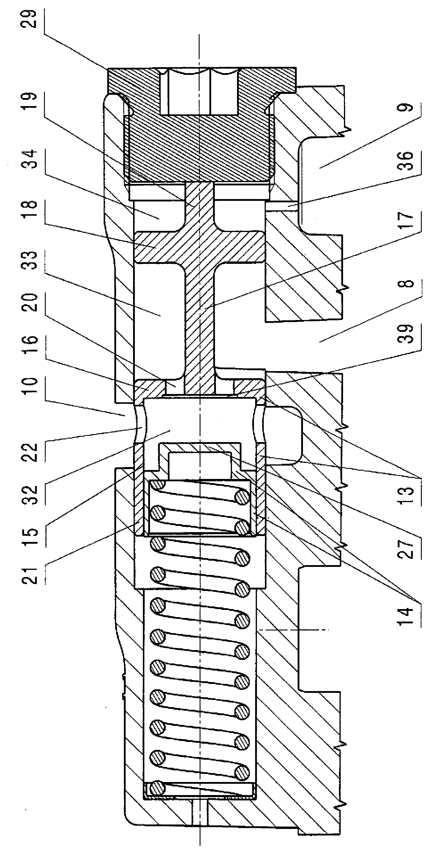
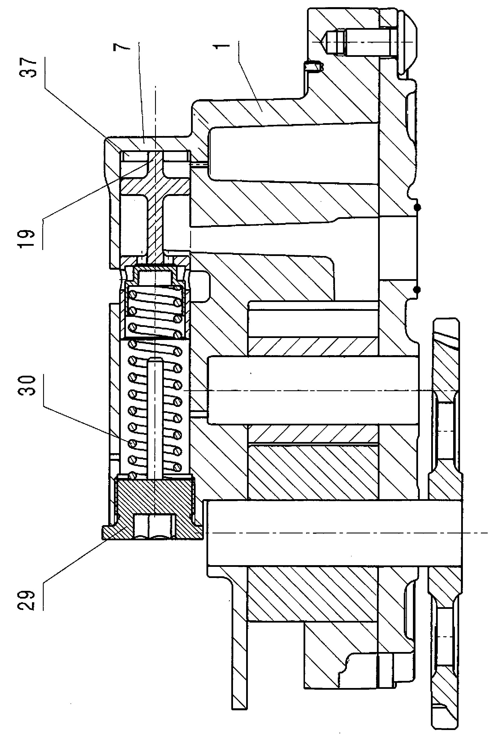
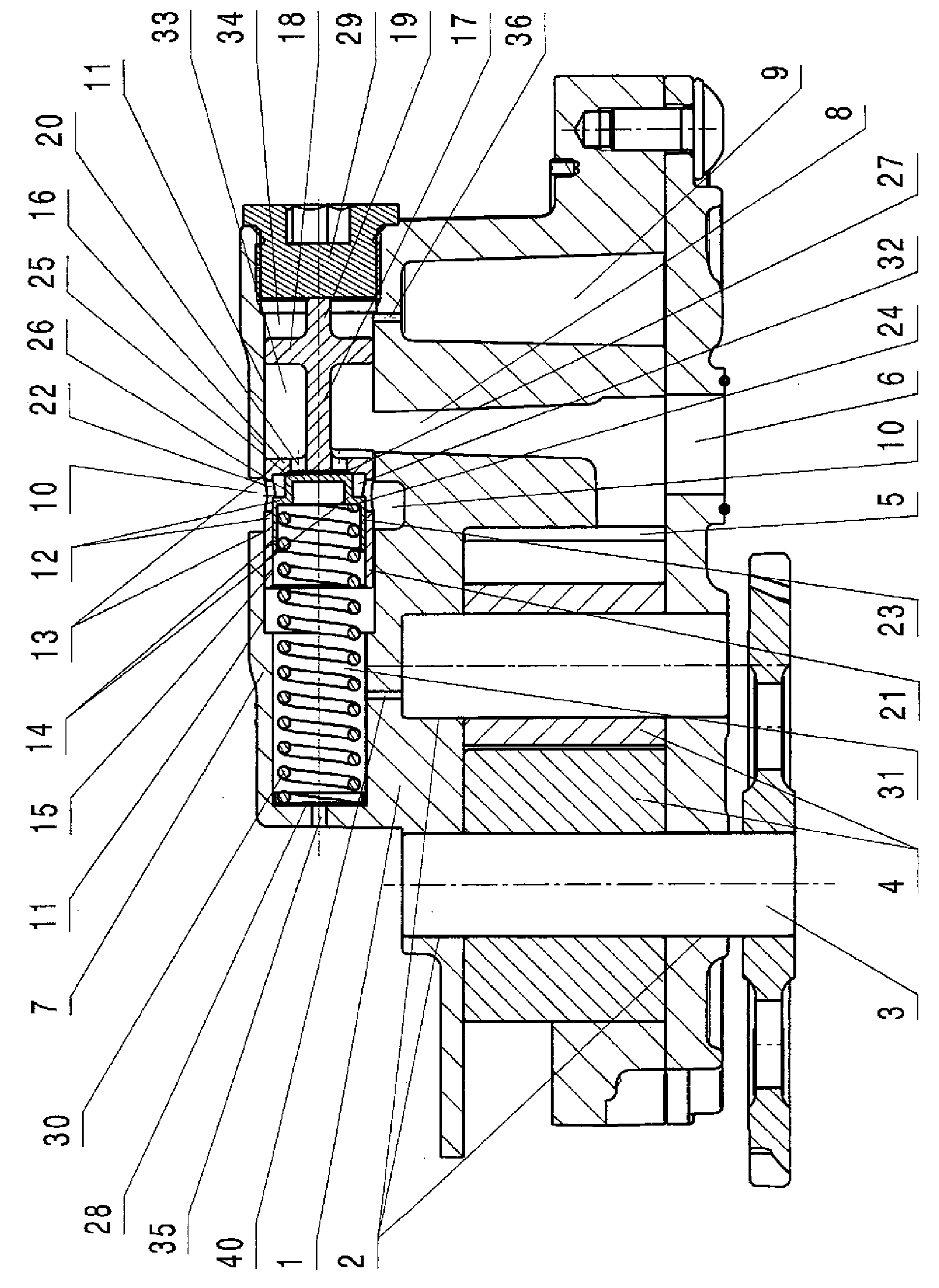
[0025] The pump housing 1 shown in FIG. 1 has: a bearing point 2; a rotating wheel set (Laufradsatz) 4 (of course it can also be Similarly, other oil pump constructions, such as a rotary wheel set of a cycloidal rotor pump), which have pressure waists (Druckniere) 5 arranged in the pressure region of the pump housing 1; Pressure connection channel (Druckanschlusskanal) 6 arranged at the pump housing 1 with a valve seat 7 arranged at the pump housing 1, a pressure channel 8 arranged between the valve seat 7 and the pressure connection channel 6, arranged at Control channel 9 between valve seat 7 and passage and overflow channel 10 arranged between valve seat 7 and oil sump; with piston guide 11 arranged in valve seat 7 in pump housing 1 Double piston 12 with an outer adjusting piston 13, in which an inner piston guide for the inner piston is arranged, wherein a piston rod 17 with at least one working piston 18 is arranged on the adjusting piston, the piston rod 17 is arranged i...


PUM


Abstract

The invention relates to a lubricant valve for oil pumps of internal combustion engines, in order to supply the bearings and sliding surfaces of the engines with lubricant in an optimum manner in order to reduce the wear. The invention is based on the problem of developing a lubricant valve for oil pumps of internal combustion engines, which lubricant valve combines, in particular, the functions of a cold-start valve and those of a control valve within itself with a minimum amount of installation space and is constructed in such a way that it is insensitive with respect to the wear debris and / or foundry sand which is entrained by the lubricant, in the process makes high throughflow quantities possible, in addition is of inexpensive construction in terms of production and assembly technology and can be produced inexpensively, and, moreover, always operates robustly,; reliably and insusceptible to disruptions, even under extreme use conditions. The lubricant valve according to the invention for oil pumps of internal combustion engines is distinguished, in particular, by a double piston in a piston guide of a valve seat of the pump housing, the double piston consisting of a cold-start piston which is arranged in a control piston and is arranged in a cold-start piston guide which is arranged in the control piston, wherein, lying opposite the cold-start piston guide, a piston rod is arranged on the piston head of the control piston, on which piston rod, spaced apart from the piston head of the control piston, a working piston is arranged which the piston rod protrudes beyond in the form of a spacer rod, wherein, adjacent to the working piston, inflow holes are arranged in the piston head of the control piston and, adjacent to the piston head,; outflow holes are arranged in the cylinder wall of the cold-start piston guide of the control piston.

Description

technical field [0001] The invention relates to a lubricant valve for an oil pump of an internal combustion engine in order to optimally supply lubricant to bearings and sliding surfaces of the engine in order to reduce wear. Background technique [0002] In practice, especially for motor vehicle engine construction, the most different lubricant valves are known. [0003] In order to avoid pressure peaks during the starting phase of the engine and to minimize wear on the engine, a valve is arranged in the lubricant circuit in the direction of flow of the lubricant after the oil pump, which acts as a cold start valve during the starting phase of the engine ( Since cold lubricants have a high viscosity) open and avoid pressure peaks until the lubricant has heated to such an extent that regulation of its viscosity is ensured via a further regulating valve arranged in the oil circuit. [0004] In addition to the cold start valve, the control valve is required in the oil circuit...

Claims


Application Information

Patent Timeline
Patent Type & Authority Applications(China)
IPC IPC(8): F04C2/14
CPCF01M1/16F04C2/14F04C15/0088F04C14/06F04C14/24Y10T137/85986F01M1/02
Inventor T.施泰纳E.施密特
Owner NIDEC GPM GMBH
Why Eureka
Try Eureka