

Fluorescence sensor
A fluorescent sensor and fluorescent technology, applied in the field of fluorescent sensors, can solve the problems that the fluorescent sensor 110 is not easy to obtain high detection sensitivity, etc.
- Summary
- Abstract
- Description
- Claims
- Application Information
AI Technical Summary
Problems solved by technology
Method used
Image

Examples
no. 1 Embodiment approach >
[0037] Hereinafter, the fluorescence sensor 10 according to the first embodiment of the present invention will be described.
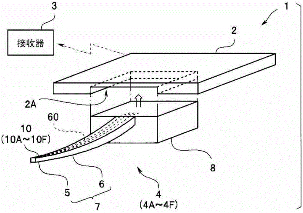
[0038] Such as image 3 As shown, the needle-type fluorescence sensor 4 having the fluorescence sensor 10 constitutes the sensor system 1 together with the main body 2 and the receiver 3.
[0039] That is, the sensor system 1 includes a needle-type fluorescence sensor 4, a main body portion 2, and a receiver 3 that receives and stores signals from the main body portion 2. The signal transmission and reception between the main body 2 and the receiver 3 is performed wirelessly or wiredly.
[0040] The needle-type fluorescence sensor 4 includes a needle portion 7 having a needle tip portion 5 and an elongated needle body portion 6. The tip portion 5 includes a fluorescence sensor 10 as a main functional portion; it is integrated with the rear end portion of the needle body portion 6 化的 Connector Section 8. The needle tip portion 5, the needle body portion 6, an...
no. 2 Embodiment approach >
[0097] Next, the needle-type fluorescence sensor 4B having the fluorescence sensor 10B of the second embodiment of the present invention will be described. The fluorescence sensor 10B of this embodiment is similar to the fluorescence sensor 10 of the first embodiment, and therefore, the same components are assigned the same reference numerals, and the description is omitted.
[0098] Such as Picture 8 As shown, the fluorescence sensor 10B is formed on the side surface 24 (wall surface 45 of the through hole 46 of the frame-shaped substrate 40) of the concave portion 23 of the detection substrate portion 20B as the PD element 13A as the first photoelectric conversion element, and is also formed on the concave portion 23 A PD element 13B as a second photoelectric conversion element is formed on the bottom surface 22 (the upper surface of the wiring board 30B).
[0099] A silicon oxide layer 42B as a third protective layer for protecting the PD element 13B and a filter 41B are arrang...
no. 3 Embodiment approach >
[0117] Next, the needle-type fluorescence sensor 4D having the fluorescence sensor 10D of the third embodiment of the present invention will be described. The fluorescence sensor 10D of this modification example is similar to the fluorescence sensor 10 of the first embodiment and the like. Therefore, the same components are assigned the same reference numerals, and the description is omitted.
[0118] The detection substrate portion 20D of the fluorescence sensor 10D is integrally manufactured with a silicon wafer 20DW as a semiconductor substrate. That is, the concave portion 23D of the detection substrate portion 20D is, for example, a concave portion formed on the first main surface 21 of the silicon wafer 20DW by an etching method.
[0119] Next, use Figure 10A~Figure 10E , The manufacturing method of the fluorescence sensor 10D will be described. In addition, in Figure 10A~Figure 10E The middle is a partial cross-sectional view of the area of one fluorescence sensor 10D...
PUM
 Abstract
Description
Claims
Application Information