Arc oscillation-based gas shielded welding arc tracking method

A technology of gas shielded welding and arc, which is applied in the direction of arc welding equipment, welding equipment, manufacturing tools, etc., can solve the problems of welding current jump, influence on arc stability, spatter, etc. Flexible, reducing the effect of signal mutations

Active Publication Date: 2013-07-03
SHENYANG INST OF AUTOMATION - CHINESE ACAD OF SCI
View PDF6 Cites 33 Cited by
  • Summary
  • Abstract
  • Description
  • Claims
  • Application Information

AI Technical Summary

Problems solved by technology

The general mechanical tracking accuracy is relatively low, and affected by the surface roughness of the weldment, the tracking probe wears seriously
Laser visual tracking with relatively high precision is easily affected by smoke and dust in the welding process, and the image collector is easily interfered by welding arc light
In addition, these two tracking methods require an additional tracking device at the end of the welding torch, which reduces the flexibility of the welding torch
The mechanism of arc tracking is simple and easy to operate. However, ordinary arc tracking needs to be equipped with a filter to physically filter the sampling signal, which prolongs the signal response time.
[0003] The ideal welding current curve is smooth, but in actual welding, there will be splashes, short circuits and other phenomena that affect the stability of the arc. At this time, the welding current will jump instantaneously (generally only 1 to 2 sampling values)
However, this instantaneous value cannot reflect the overall change law of the welding current curve, which is wrong. At the same time, it will affect the filtering result of this interval. If the result is at the peak or valley position (characteristic point), it will affect the deviation. judge

Method used


Image

  • Arc oscillation-based gas shielded welding arc tracking method
  • Arc oscillation-based gas shielded welding arc tracking method
  • Arc oscillation-based gas shielded welding arc tracking method

Examples


Embodiment Construction

[0038] The present invention will be further described in detail below in conjunction with the accompanying drawings and embodiments.

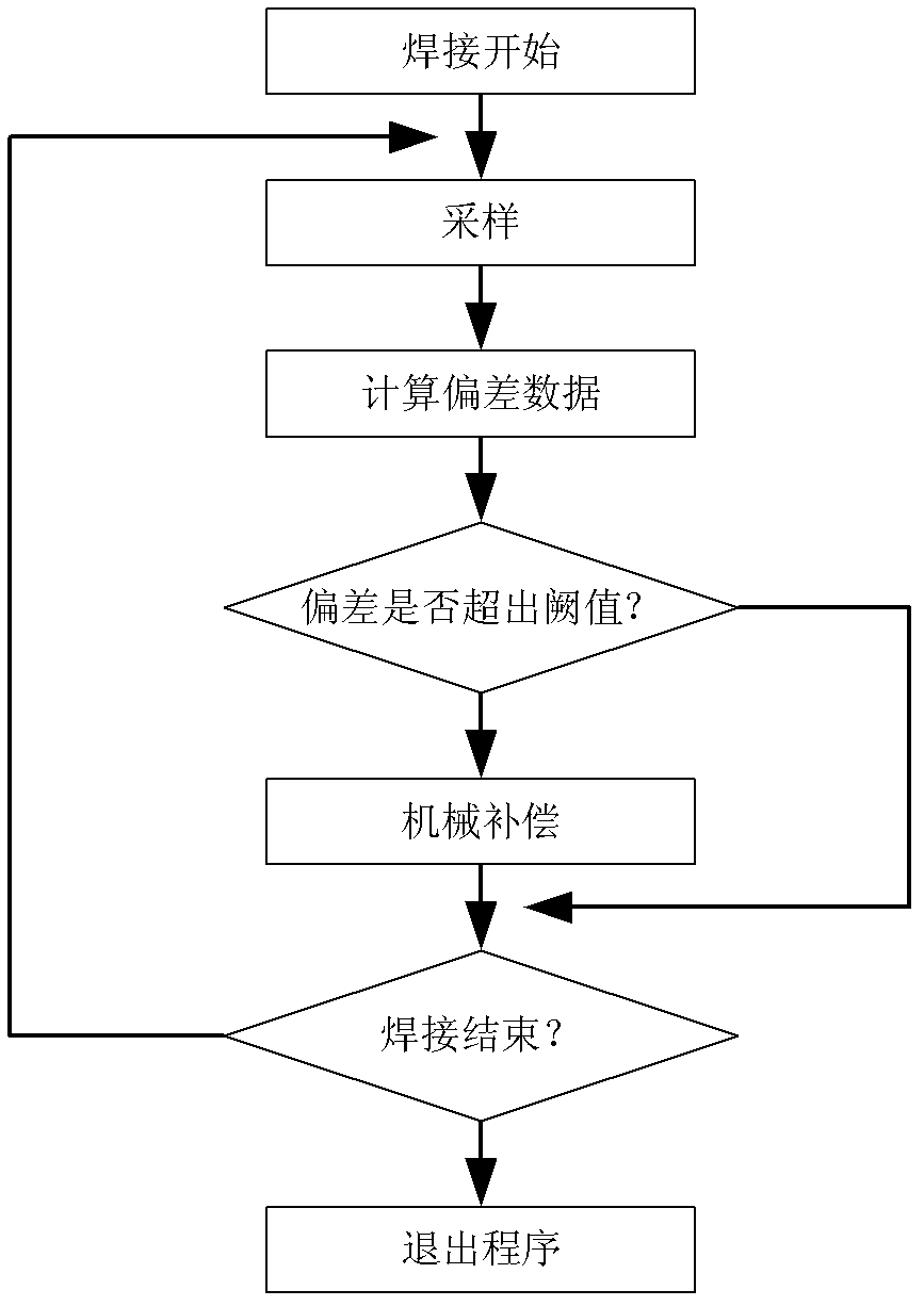
[0039] The present invention is a gas shielded welding arc tracking method based on arc swing, such as figure 1 shown, including the following steps:

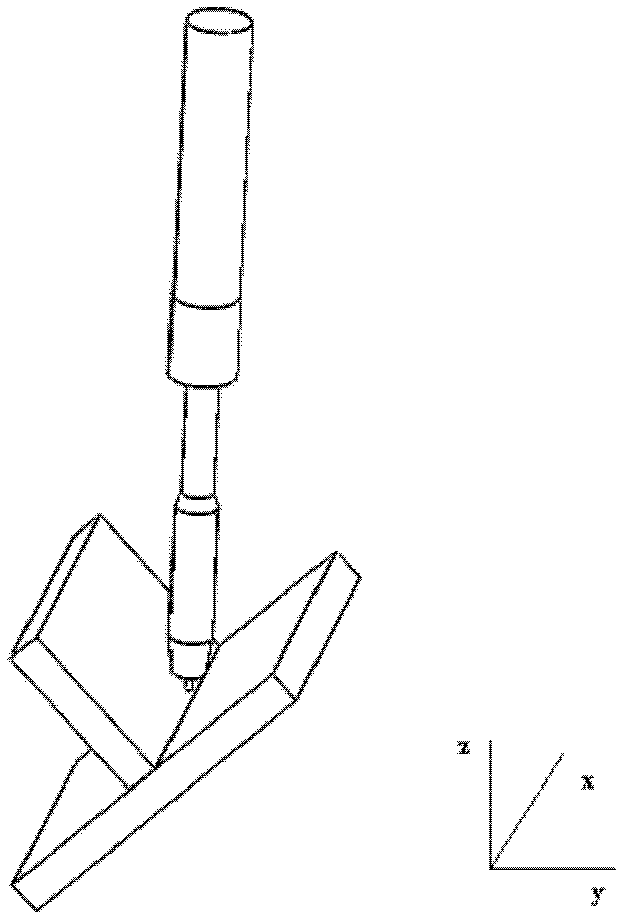
[0040] 1) After the welding starts, the welding torch starts to swing periodically in the direction perpendicular to the weld seam.

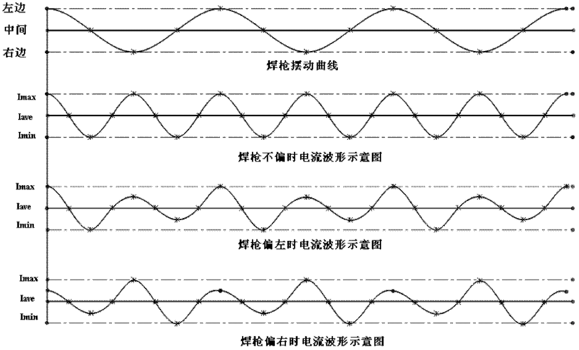
[0041] The trigger signal for the torch swing is controlled by the sampling process. The current sensor triggers the welding torch to swing in a specific direction (left or right) while sampling, so that the current change period can be synchronized with the swing direction of the welding torch, that is, the sampling of the welding current is performed synchronously with the swing of the arc. After a deviation occurs, the swing direction of the welding torch can be judged by the periodic coordinates, and the direction of the deviation can be determined in the f...


PUM


Abstract

The invention relates to an arc oscillation-based gas shielded welding arc tracking method which comprises the following steps that after the welding is started, a welding gun starts doing a periodic oscillation along a direction vertical to a weld joint; a current sensor carries out real-time sampling on a welding current; sampled data is filtrated; filtered data is subjected to deviation judgment and converted into deviation data; and the deviation data is converted into a movement command, and a weld joint track is compensated in real time through a deviation rectifying device. Because sampled signals are filtered by adopting software, the arc oscillation-based gas shielded welding arc tracking method is high in response speed and tracking precision; and due to the adoption of a dual-filtering mode, the signal mutation caused by instable arc is reduced, the deviation compensation dosage is calculated by using known welding parameters, the support of a database or expert system is not needed, the requirement of a welding device on a weldment processing precision is lowered, and thus the arc oscillation-based gas shielded welding arc tracking method is an effective means for realizing the flexible automatic welding.

Description

technical field [0001] The invention relates to a gas shielded welding arc tracking method based on arc swing, which is used to solve the problem of path deviation between welding torch trajectory planning and actual welding bead. Background technique [0002] As an important technology of welding automation equipment, weld seam tracking mainly solves the problem of welding torch movement trajectory deviation caused by positioning accuracy, weldment processing accuracy, weldment size repeatability and thermal stress during welding. The general mechanical tracking accuracy is relatively low, and the tracking probe wears seriously due to the influence of the surface roughness of the weldment. Laser visual tracking with relatively high precision is easily affected by smoke and dust in the welding process, and the image collector is easily interfered by welding arc light. In addition, both of these two tracking methods require an additional tracking device at the end of the wel...

Claims


Application Information

Patent Timeline
Patent Type & Authority Applications(China)
IPC IPC(8): B23K9/127
Inventor 王琛元柳连柱吴强邹媛媛赵明扬
Owner SHENYANG INST OF AUTOMATION - CHINESE ACAD OF SCI
Why Eureka
Try Eureka