High density circulating fluidized bed device of four-point air-inflated structure used B category particle

A circulating fluidized bed and air-filled structure technology, applied in the field of clean energy, can solve problems such as reducing fuel conversion rate and utilization rate, hidden dangers of device safety operation, and affecting gas-solid two-phase heat and mass transfer efficiency, etc. simple effect

Active Publication Date: 2013-07-03
INST OF ENGINEERING THERMOPHYSICS - CHINESE ACAD OF SCI
View PDF4 Cites 0 Cited by
  • Summary
  • Abstract
  • Description
  • Claims
  • Application Information

AI Technical Summary

Problems solved by technology

However, current studies on high-density circulating fluidized beds have shown that due to the high particle concentration in the bed, the flow of particles in the riser is not uniform, especially at the bottom of the riser and the top region of the riser with a strongly constrained outlet structure. and axial inhomogeneities are more pronounced
This inhomogeneity seriously affects the full mixing of gas-solid two-phase and the heat and mass transfer efficiency in the bed, reduces the conversion rate and utilization rate of fuel, and brings hidden dangers to the safe operation of the device.
[0003] Through literature research, some scholars at home and abroad have done a lot of work on the experimental research of high-density circulating fluidized bed systems, and have also obtained useful conclusions. Solid particle design, research on high-density circulating fluidized beds using B-type particles still needs to be in-depth
In addition, in the existing experimental techniques or devices, there is no report of setting the inflation point at the bottom of the riser, or at the top of the riser with a strongly constrained outlet structure.

Method used


Image

  • High density circulating fluidized bed device of four-point air-inflated structure used B category particle

Examples


Embodiment Construction

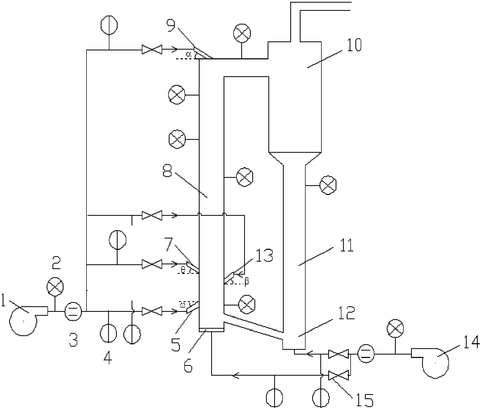
[0031] See figure 1 , is a high-density circulating fluidized bed device using B-type particles in a four-point inflatable structure of the present invention, which is composed of an air supply system, a main bed system, a separation system, a material return system and a test system. Including: two air compressors 1, 14, multiple manual valves 15, multiple pressure sensors 2, multiple temperature sensors 3, multiple mass flow meters 4, air distribution plate 6, riser pipe 8, cyclone separator 10, lower Feed pipe 11, J valve return feeder 12. Among them, three aeration points are asymmetrically distributed at the bottom of the riser 8 of the high-density circulating fluidized bed using B-type particles, and one aeration point is arranged at the top of the riser 8 above the strongly restricted outlet. Wherein the high-density circulating fluidized bed according to Grace etc. (references are: J.R.Grace, A.S.Issangya, D.Bai. 2116.) to define the standard, that is: the solid flu...


PUM


Abstract

The invention relates to a high density circulating fluidized bed device of a four-point air-inflated structure used B category particle, which relates to clean energy technology. An experiment table system comprises an air feed system, a main bed system, a gas-solid separation system and a material returning system. The air feed system is provided by an air compressor. The main bed system is formed by a wind distribution board and a lifting tube. The gas-solid separation system is formed by a cyclone separator. The material returning system is composed of a material foot and a J-valve material returning device. Three air inflation points are asymmetrically distributed on the bottom portion of the lifting tube, and an air inflation point is distributed at the position of an outlet on the top portion of the lifting tube. The high density circulating fluidized bed device can be used for river basin character analysis and mechanism survey of a high density circulating fluidized bed using the B category particle. Flow of the B category particle in the tube is even by adjusting air quantity of the air inflation points. The high density circulating fluidized bed device is simple in structure, convenient to operate, and capable of well solving the problem that particle concentration at the bottom of the lifting tube of the high density circulating fluidized bed is high so that particle flow is uneven, and the particle on the top portion of the lifting tube using a strong restrain outlet is aggregated so that the particle flow is uneven.

Description

technical field [0001] The invention relates to the technical field of clean energy, and relates to a high-density circulating fluidized bed device using B-type particles in a four-point inflatable structure. Background technique [0002] High-density circulating fluidized bed is a new generation of high-efficiency, low-pollution clean energy technology developed internationally in recent years. It has the characteristics of strong mixing, large processing capacity and wide application range. However, current studies on high-density circulating fluidized beds have shown that due to the high particle concentration in the bed, the flow of particles in the riser is not uniform, especially at the bottom of the riser and the top region of the riser with a strongly constrained outlet structure. and axial inhomogeneities are more pronounced. This inhomogeneity seriously affects the full mixing of gas-solid two-phase and the heat and mass transfer efficiency in the bed, reduces th...

Claims


Application Information

Patent Timeline
IPC IPC(8): C10J3/56
Inventor 王雪瑶徐祥肖云汉
Owner INST OF ENGINEERING THERMOPHYSICS - CHINESE ACAD OF SCI
Why Eureka
Try Eureka