
Fabric shaping/dryer energy conservation and emission reduction control system and method for textile and dying industry

A technology of energy saving, emission reduction and control system, applied in the direction of processing textile material equipment configuration, etc., can solve the problems of heat waste, energy waste, temperature, humidity, smoke concentration and wrong exhaust, to avoid energy, solve high temperature resistance, Improve the effect of printing and dyeing

Active Publication Date: 2013-07-03
李川凌
View PDF3 Cites 6 Cited by
  • Summary
  • Abstract
  • Description
  • Claims
  • Application Information

AI Technical Summary

Problems solved by technology

[0004] The current way of adjusting the temperature and humidity is through simple manual adjustment, that is, adjusting the angle of the exhaust fan to perform proper exhaust, so as to maintain the best working environment parameters in the setting machine or dryer, and this process also requires Operators detect the fabrics in real time, but they often perform wrong exhaust operations because they cannot accurately grasp the parameters of temperature, humidity, and smoke concentration in the setting machine or dryer, which makes the hot air exhaust in the system unreasonable and will not need to be exhausted The waste of heat in the hot air causes a lot of energy waste and affects the printing and dyeing effect of clothing fabrics

Method used


Image

  • Fabric shaping/dryer energy conservation and emission reduction control system and method for textile and dying industry
  • Fabric shaping/dryer energy conservation and emission reduction control system and method for textile and dying industry

Examples


Embodiment Construction

[0026]

[0027] In order to make the object, technical solution and advantages of the present invention clearer, the present invention will be further described in detail below in conjunction with the accompanying drawings.

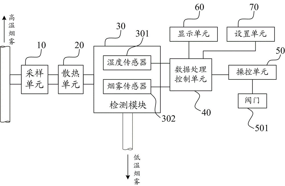
[0028] The energy-saving and emission-reduction control system for fabric setting / drying machine in the textile printing and dyeing industry according to the embodiment of the present invention includes a sampling unit, a heat dissipation unit, a detection module, a data processing control unit, a control unit, a display unit and a setting unit;

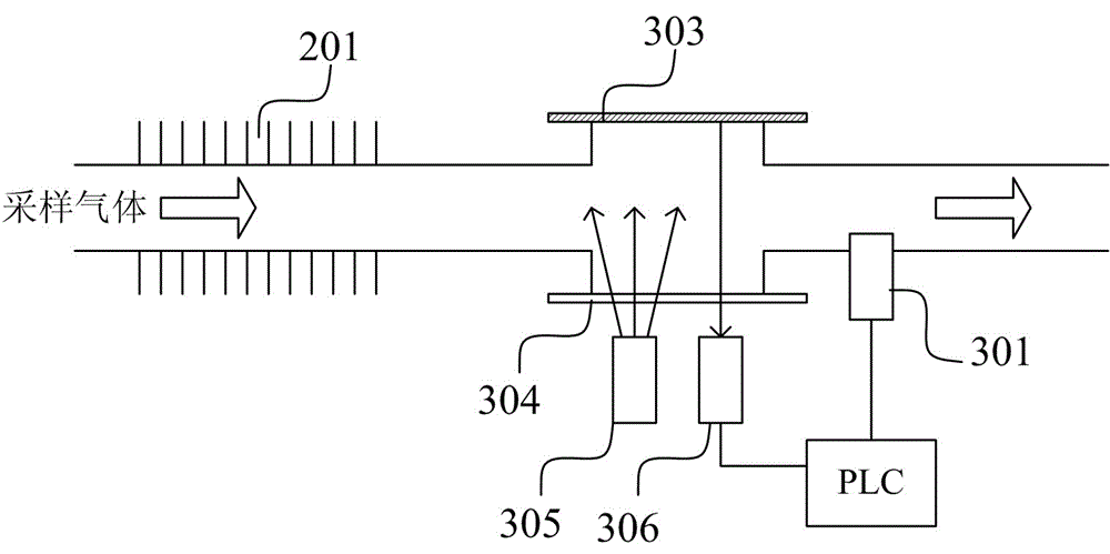
[0029] The sampling unit 10 obtains the sampled gas from the main air path of the sizing dryer, and inputs the sampled gas into the system. Since this system is applied to the sizing or drying machine for fabrics in the textile printing and dyeing industry, the gas produced is The temperature of high temperature gas ranges from 150°C to 250°C, which is not conducive to the normal operation of ordinary humidity s...


PUM


Abstract

An embodiment of the invention discloses a fabric shaping / dryer energy conservation and emission reduction control system for the textile and dying industry. The control system comprises a sampling unit, a radiating unit, a detection module, a data processing control unit, a control unit, a display unit and a setting unit, wherein the sampling unit obtains sampling gas, and the sampling gas is cooled by the radiating unit; the data processing control unit compares values, detected by a humidity sensor and / or a smoke sensor, of the cooled sampling gas with a set value; and a control signal is output to control the opening degree of an exhaust valve, so that exhaust operation is performed. The embodiment of the invention further discloses a clothes shaping and drying energy conservation and emission reduction control method. When the control system and method are adopted, the problem that the humidity sensor or the smoke sensor are not high temperature resistant is solved, the detection values of the humidity sensor and / or the smoke sensor are chosen to be compared with a set value according to different technologies, and the opening degree of the exhaust valve is controlled, so that optimal working parameters are maintained, and a large amount of energy is avoided from being consumed by exhaust by mistake.

Description

technical field [0001] The invention relates to an energy-saving and emission-reduction control system, in particular to an energy-saving and emission-reduction control system and method for setting (dryer) in the textile printing and dyeing industry. Background technique [0002] In the textile printing and dyeing industry, shaping and drying is the main process of finishing. The knitted fabric can achieve a certain shrinkage, density, and hand feeling through the mechanical action of the shaping machine and the anti-shrinkage, softening, and hardening effects of chemical reagents. And achieve uniform door width, smooth lines, clear lines and other aesthetic effects. [0003] In the shaping or drying process, the control requirements for temperature and humidity are relatively strict. Since different fabrics have different requirements for humidity or temperature, the humidity of different fabrics is controlled at about 50% to 90%, and the temperature is controlled at about...

Claims


Application Information

Patent Timeline
Patent Type & Authority Applications(China)
IPC IPC(8): D06B23/20
Inventor 李川凌
Owner 李川凌
Learn More