Thermal pressure relief device with expansion activation

一种泄压、设备的技术,应用在热泄压设备(TPRD)领域,能够解决单向形状记忆触发机构昂贵等问题

Active Publication Date: 2013-07-03
GM GLOBAL TECH OPERATIONS LLC
View PDF5 Cites 0 Cited by
  • Summary
  • Abstract
  • Description
  • Claims
  • Application Information

AI Technical Summary

Problems solved by technology

This one-way shape memory trigger mechanism is expensive and involves several moving parts

Method used


Image

  • Thermal pressure relief device with expansion activation
  • Thermal pressure relief device with expansion activation
  • Thermal pressure relief device with expansion activation

Examples


Embodiment Construction

[0048] The following detailed description and drawings describe and illustrate various exemplary embodiments of the invention. The description and drawings are intended to enable a person skilled in the art to make and use the invention and are by no means intended to limit the scope of the invention.

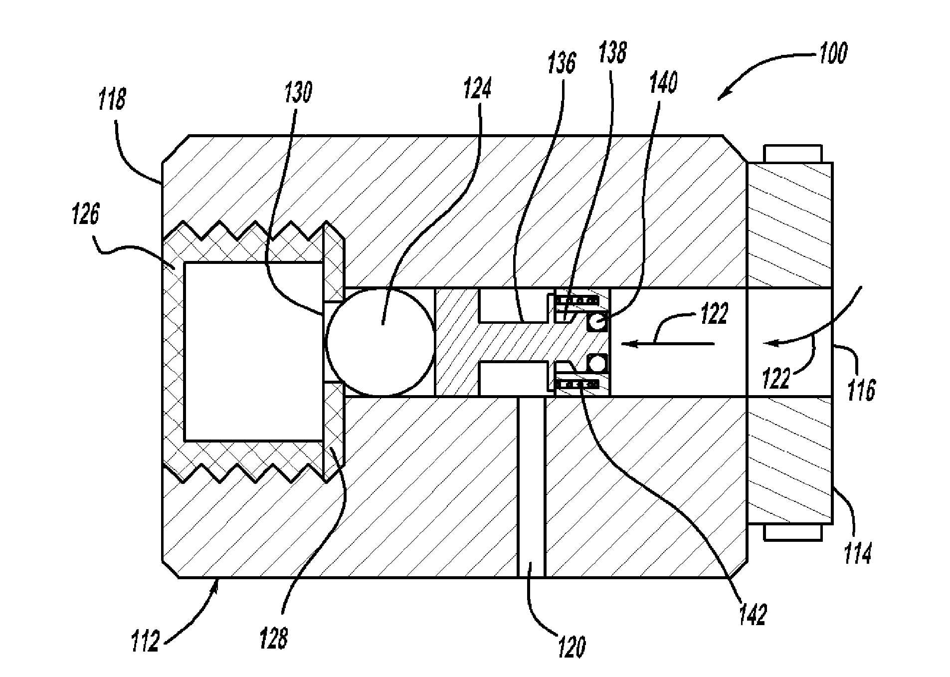
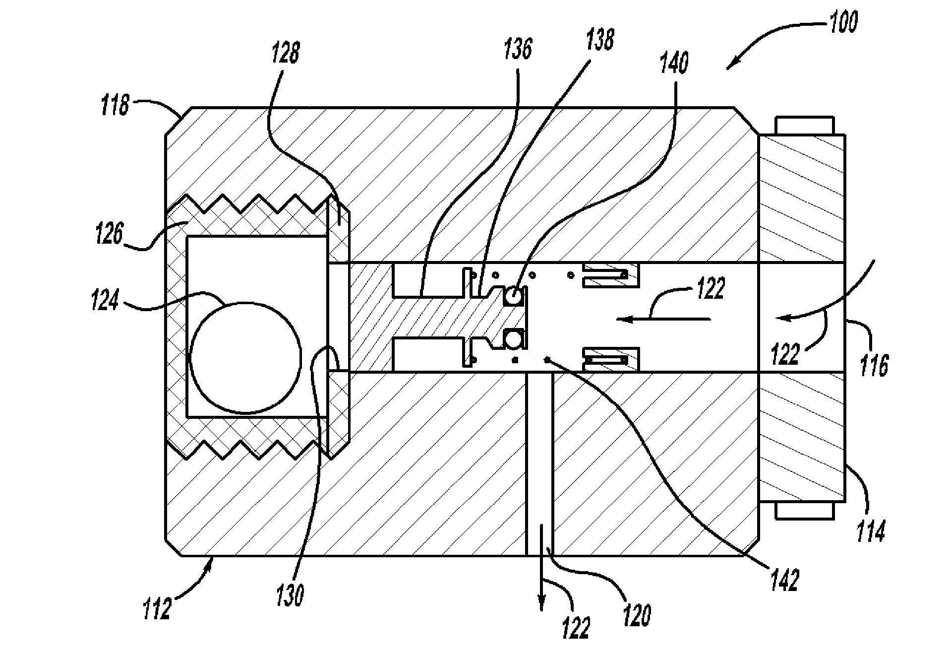
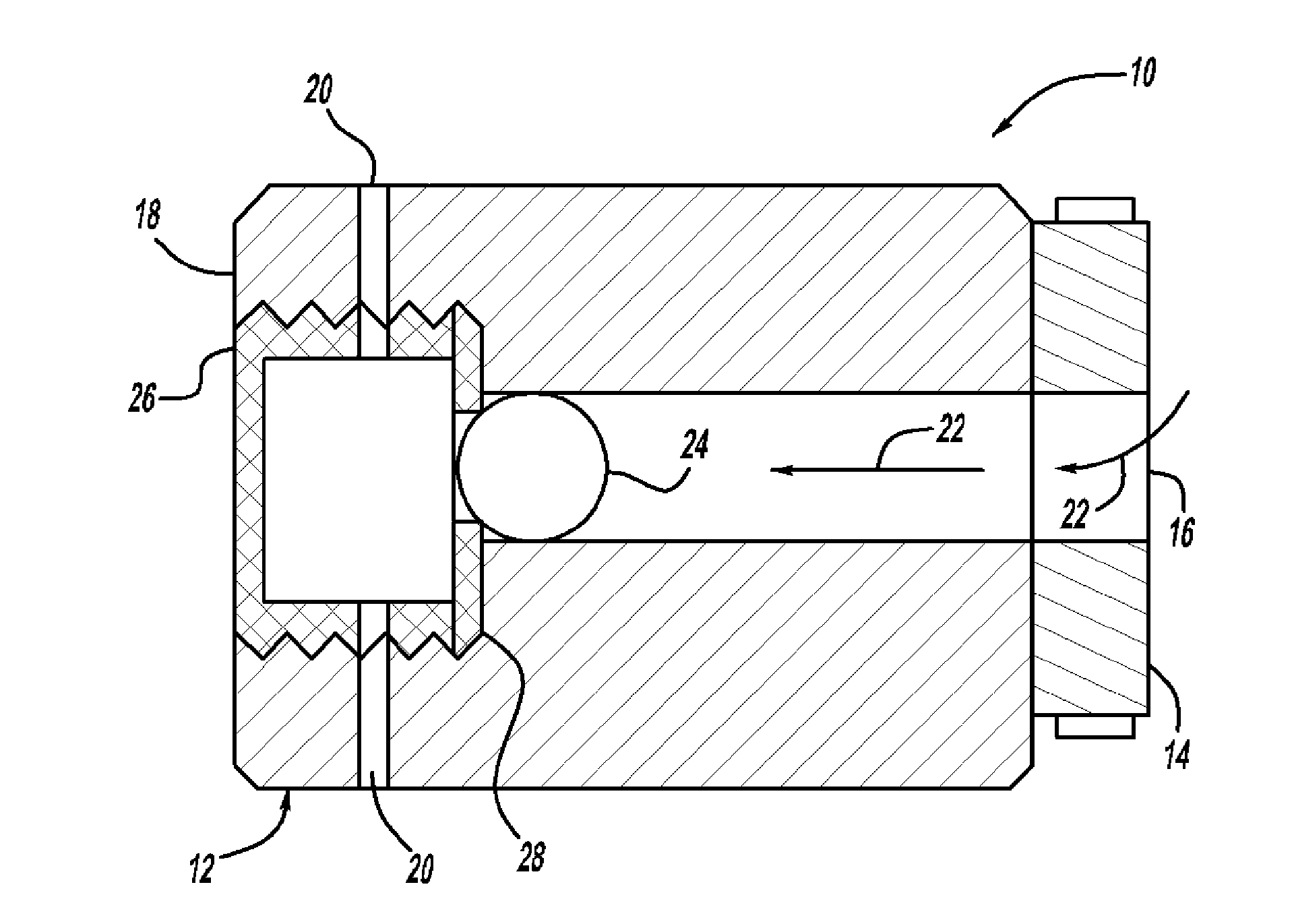
[0049] In FIGS. 1 and 2 , a thermal pressure relief device (TPRD) 10 is shown comprising a housing 12 having a first end 14 with a first aperture 16 and a second end with a second aperture 20 18. First aperture 16 and second aperture 20 are configured to allow fluid 22 to flow through housing 12 . In one example, when the TPRD is activated as shown in FIG. 2 , fluid 22 may flow from a high pressure vessel (not shown) in fluid communication with first aperture 16 through housing 12 and second aperture 20 to the ambient atmosphere. Housing 12 may, for example, be configured to be threadably engageable with a high-pressure vessel.

[0050] TPRD 10 includes a trigger member 24 d...


PUM


Abstract

A thermal pressure relief device (TPRD) is shown and includes a housing having a first end with a first aperture and a second end having a second aperture. The first and second apertures are configured to allow a fluid to flow through the housing. The TPRD includes a trigger member, such as a ball, disposed within the housing. The ball is seated laterally within a retainer. The retainer includes a rim forming a seat for supporting the ball within the housing. The movement of the ball from the first closed position laterally seated within the retainer to the second open position descended within the retainer is caused by an expansion of the rim of the retainer. The rim of the retainer is formed substantially of a temperature sensitive material adapted to expand volumetrically with an increase in temperature. The temperature sensitive material can expand linearly or non-linearly.

Description

technical field [0001] The present disclosure relates to thermal pressure relief devices (TPRDs), and more particularly, to TPRDs for high pressure vessels. Background technique [0002] Fuel cells have been proposed for various applications as clean, efficient, and environmentally friendly power sources. A plurality of fuel cells may be arranged to form a fuel cell stack capable of powering an electric vehicle. One example of a fuel cell is a proton exchange membrane (PEM) fuel cell. In a PEM fuel cell, hydrogen is supplied to the anode as fuel and oxygen is supplied to the cathode as oxidant. The usual technique for storing hydrogen is in lightweight, high-pressure containers that are puncture-resistant. High-pressure vessels containing compressed hydrogen must have the desired mechanical stability and integrity that prevent uncontrolled release of the compressed gas from the pressure vessel due to internal pressure. It is also generally desirable to keep the pressure ...

Claims


Application Information

Patent Timeline
Patent Type & Authority Applications(China)
IPC IPC(8): F16K17/38
CPCF16K17/383H01M8/04089Y10T137/7737Y10T137/1797Y10T137/1812Y02E60/50
Inventor J.舒尔策
Owner GM GLOBAL TECH OPERATIONS LLC
Why Eureka
Try Eureka