Anti-abrasion and attrition-reducible circulating fluidized bed boiler

A circulating fluidized bed and anti-wear technology, which is applied in the direction of fluidized bed combustion equipment, burning fuel in a molten state, lighting and heating equipment, etc., can solve the problem that the inner wall of the boiler cannot be protected, and the wear of protrusions such as welding seams cannot be solved. , The layout method of anti-wear and wear-reducing devices is unclear, etc., to achieve a good anti-wear effect

Active Publication Date: 2013-07-03
刘少光
View PDF7 Cites 7 Cited by
  • Summary
  • Abstract
  • Description
  • Claims
  • Application Information

AI Technical Summary

Problems solved by technology

[0008] For this reason, the technical problem to be solved by the present invention is that the layout method of the anti-wear and anti-friction devices of circulating fluidized bed boilers in the prior art is not clear, which is not conducive to realizing the anti-wear and anti-wear performance of the boiler while not affecting the heating performance of the boiler. To achieve the best anti-wear effect, in addition, it cannot solve the problem of wear at the protrusions such as welding seams, and cannot provide good protection for all parts of the inner wall of the boiler, thereby providing an easy-to-operate, well-considered welding seam, etc. Abrasion-resistant and wear-reducing circulating fluidized bed boilers that can achieve good protection against the wear at the protrusions and the entire inner wall of the boiler

Method used


Image

  • Anti-abrasion and attrition-reducible circulating fluidized bed boiler
  • Anti-abrasion and attrition-reducible circulating fluidized bed boiler
  • Anti-abrasion and attrition-reducible circulating fluidized bed boiler

Examples


Embodiment Construction

[0045] In the following, the present invention will be further described by using the following embodiments in conjunction with the accompanying drawings.

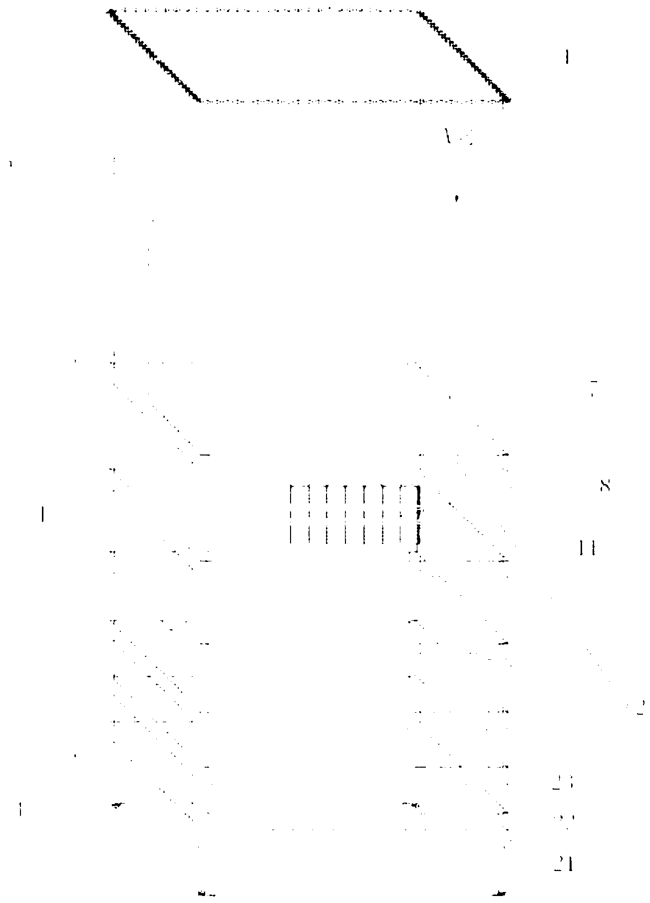
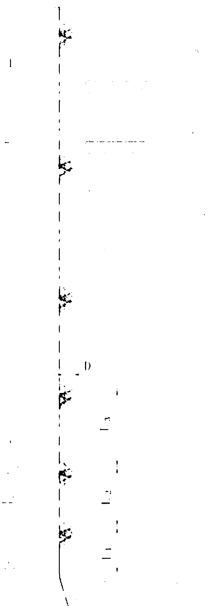
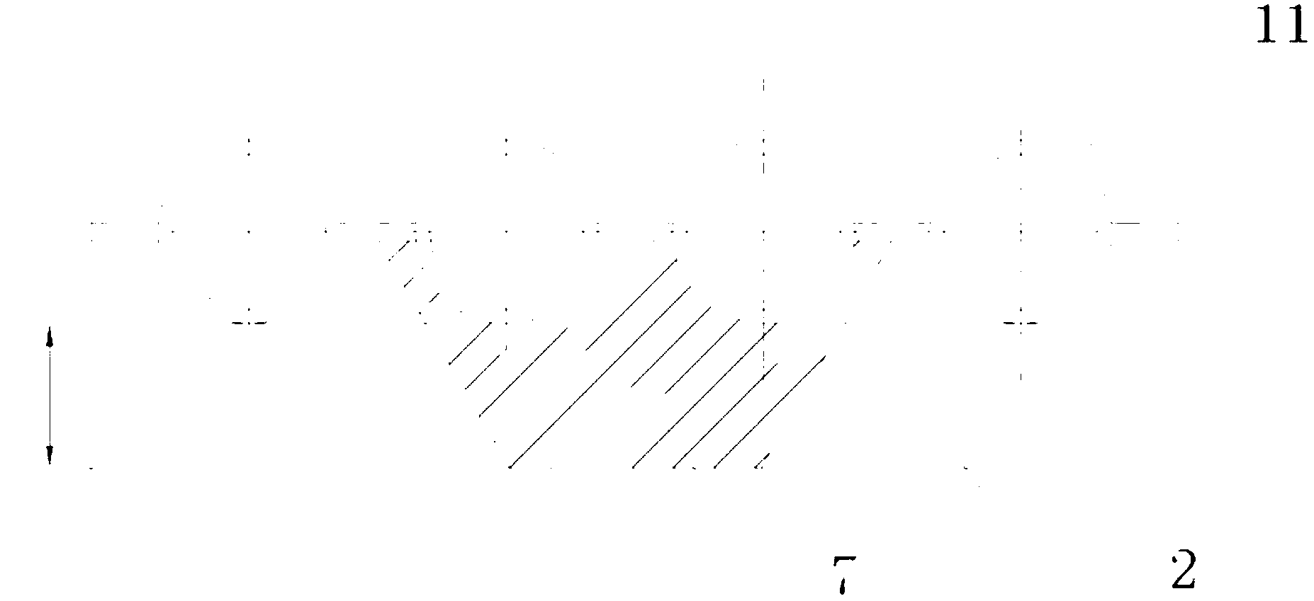
[0046] like figure 1 As shown, the anti-friction circulating fluidized bed boiler described in this embodiment includes a number of water-cooled wall tubes 11 forming the furnace water-cooled wall 1, and the water-cooled wall 1 is provided with several channels from bottom to top connected with the water-cooled wall. The horizontal choke beam 2 vertical to the length direction of the wall pipe 11, the position of the horizontal choke beam 2 on the water wall 1 satisfies the exponential formula a n+1 -(L+1)a+L=0, wherein, the a is the base number, the n is the number of the horizontal flow blocking beam 2, and the L is the wear-resistant plastic upper edge 4 to The distance along the lower edge of the furnace outlet 5.

[0047] In this embodiment, the distance L from the upper edge of the wear-resistant plastic in the den...


PUM


Abstract

The invention provides an anti-abrasion and attrition-reducible circulating fluidized bed boiler. The circulating fluidized bed boiler comprises a plurality of water wall tubes for forming a furnace water wall, wherein a plurality of horizontal flow blocking beams perpendicular to the water wall tubes in the length direction are arranged on the water wall; the positions of the horizontal flow blocking beams on the water wall meets an exponential formula that a<n+1>-(L+1)*a+L is equal to U; the value of the a can be obtained by using a mathematical Newton secant method; the root of a being equal to 1 is omitted to obtain a first horizontal flow blocking beam; the distance between the first horizontal flow blocking beam and an anti-abrasion plastic upper edge of a dense-phase zone is a; the distance between a second horizontal flow blocking beam and the first horizontal flow blocking beam is a<2>; and so on, the distance between a nth horizontal flow blocking beam and a (n-1)th horizontal flow blocking beam is a<n>. According to the invention, the horizontal flow blocking beams are arranged in the boiler, do not obviously affect rated operating parameter of the boiler, can effectively reduce abrasion of grains on the water wall tubes, and can reduce abrasion effect of swirl, turbulence, swirl flow, angle gather and the like, and can realize an excellent protective effect on the whole inner wall of the boiler.

Description

technical field [0001] The invention relates to a circulating fluidized bed boiler for antiwear and wear reduction, and belongs to the technical field of antiwear and antiwear for circulating fluidized bed boilers. Background technique [0002] Using the two-phase flow of solid phase and gas phase, the solid material burned in the furnace will continue to boil and expand under the action of wind, some of the particles will be collected by the gas-solid separation device at the furnace outlet, and sent back to the furnace through the return device Repeated cycle combustion, the boiler of this combustion cycle process is called circulating fluidized bed boiler. Compared with traditional boilers, circulating fluidized bed boilers have the advantages of wide fuel adaptability, sufficient combustion, large load adjustment range, fast adjustment speed, high comprehensive utilization rate of ash and slag, and low emissions of sulfur dioxide and nitrogen oxides. Therefore, Has a go...

Claims


Application Information

Patent Timeline
Patent Type & Authority Applications(China)
IPC IPC(8): F23C10/18
Inventor 刘少光刘沁昱
Owner 刘少光
Why Eureka
Try Eureka