Preparation method and structure of welding spot

A solder joint preparation and solder joint technology, which is applied in the field of solder joint preparation method and its structure, can solve the problems such as the slow rate of decline in the strength of copper core solder joints, and achieve the effect of low cost and high reliability

Inactive Publication Date: 2013-07-03
SHANGHAI INST OF MICROSYSTEM & INFORMATION TECH CHINESE ACAD OF SCI
View PDF3 Cites 10 Cited by
  • Summary
  • Abstract
  • Description
  • Claims
  • Application Information

AI Technical Summary

Problems solved by technology

[0007] In the study of mechanical properties, the shear and tensile solder joint strengths of tin-lead solder balls and copper-core solder balls tend to decrease with the increase of solid-state heat treatment time, but the strength decline rate of copper-core solder joints is slower

Method used


Image

  • Preparation method and structure of welding spot
  • Preparation method and structure of welding spot
  • Preparation method and structure of welding spot

Examples


Embodiment Construction

[0029] Embodiments of the present invention are described below through specific examples, and those skilled in the art can easily understand other advantages and effects of the present invention from the content disclosed in this specification. The present invention can also be implemented or applied through other different specific implementation modes, and various modifications or changes can be made to the details in this specification based on different viewpoints and applications without departing from the spirit of the present invention.

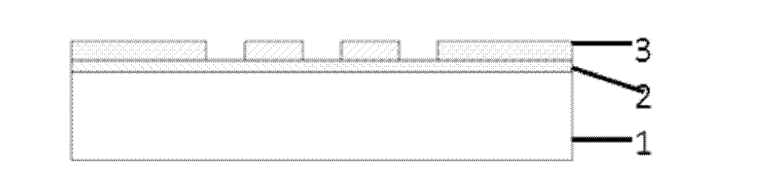
[0030] see Figures 1a-1f shown. It should be noted that the diagrams provided in this embodiment are only schematically illustrating the basic idea of ​​the present invention, and only the components related to the present invention are shown in the diagrams rather than the number, shape and shape of the components in actual implementation. Dimensional drawing, the type, quantity and proportion of each component can be changed arbitr...


PUM


Abstract

The invention provides a preparation method and a structure of a welding spot. The preparation method of the welding spot comprises the following steps that firstly, a metal layer (2) is sputtered on the front face of a silicon wafer (1) to serve as an electroplating seed layer; secondly, photoresist (3) is coated on the metal layer (2) and pre-baked; thirdly, the photoresist is imaged and then is post-baked; fourthly, the imaged photoresist is used as a covering film, copper is electroplated to form a copper layer until the thickness of the copper layer exceeds the thickness of the photoresist layer, and an umbrella-shaped copper cylinder structure (4) is formed; fifthly, the photoresist (3) is still used as the covering film, and tin is electroplated to form a tin layer (5) covering the umbrella-shaped copper cylinder structure (4); and sixthly, return flow is carried out, and a welding spot structure covering an umbrella-shaped copper cylinder is formed. The structure of the welding spot has the advantages of being low in cost, and high in reliability of shearing force and thermal machinery.

Description

technical field [0001] The patent of the present invention relates to a method for preparing solder joints and its structure, which is applied to the technical fields of electronic packaging such as flip-chip soldering using solder joints and chip size packaging. Background technique [0002] In electronic packaging technology, flip-chip soldering of solder balls and other packaging forms are used. It is different from traditional packaging forms in that it connects the chip and the substrate through solder joints instead of using metal wires. This difference enables flip-chip bonding to provide good electrical connection and other properties, and has a high packaging density. [0003] Flip-chip bonding uses solder ball reflow to connect the chip to the substrate. In the traditional packaging form, external force is used to bond the metal wires on the chip. This external force may damage the wiring or circuit in the chip, thereby causing failure. However, flip-chip solderi...

Claims


Application Information

Patent Timeline
Patent Type & Authority Applications(China)
IPC IPC(8): H01L21/60H01L23/488B23K1/00
CPCH01L24/13H01L2224/13H01L2224/13147H01L2224/136H01L2924/01322H01L2924/014H01L2924/00H01L2924/00012
Inventor 宁文果罗乐徐高卫朱春生
Owner SHANGHAI INST OF MICROSYSTEM & INFORMATION TECH CHINESE ACAD OF SCI
Why Eureka
Try Eureka