A downlink coordinated multi-point transmission method and system
A technology of multi-point transmission and cooperative reception, applied in the field of communication, can solve problems such as undiscovered, and achieve the effects of reducing interference power, improving system performance, and improving signal-to-noise ratio
- Summary
- Abstract
- Description
- Claims
- Application Information
AI Technical Summary
Problems solved by technology
Method used
Image

Examples
Embodiment 1
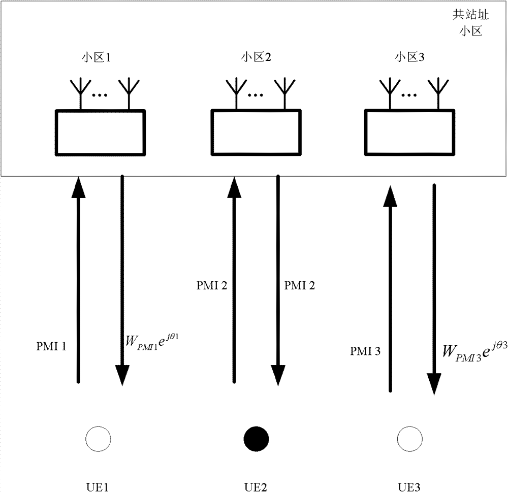
[0056] figure 2 It is a schematic diagram of the interference elimination method between co-sited cells in the present invention; in this embodiment:
[0057] Cells 1, 2, and 3 are located on the same base station site, and information exchange between cells can be performed directly without the need to exchange information through a BackHaul (backhaul) link between cells.
[0058] For UE1, UE2 and UE3, their serving cells are cell 1, cell 2 and cell 3 respectively. When cell 2 serves UE2, the cooperative cells are cell 1 and cell 3, that is, UE2 is the target receiving end, UE1 and UE3 are respectively the cooperative receiving end, the base station of cell 2 is the serving transmitting end, and the base stations of cell 1 and cell 3 are Its cooperative transmitter.
[0059] Each UE feeds back the optimal PMI to its serving cell. For example, UE1, UE2, and UE3 feed back PMI1, PMI2, and PMI3 to cell 1, cell 2, and cell 3 respectively, and the corresponding precoding vectors...
Embodiment 2
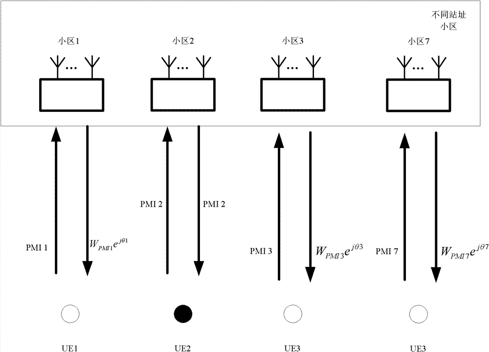
[0076] image 3 It is a schematic diagram of an interference elimination method between different site cells in the present invention; in this embodiment:
[0077] Cells 1, 2, and 3 are located on the same base station site, and information exchange between cells can be performed directly without BackHaul.
[0078] The base station sites of cell 7 and cell 1 are different, and information exchange between cells needs to pass BackHaul.
[0079] For UE1, UE2, UE3 and UE7, their serving cells are cell 1, cell 2, cell 3 and cell 7 respectively. When cell 2 serves UE2, the coordinated cells are cell 1, cell 3 and cell 7.
[0080] Each UE feeds back the optimal PMI to its serving cell. For example, UE1, UE2, UE3, and UE7 feed back PMI1, PMI2, PMI3, and PMI7 to cell 1, cell 2, cell 3, and cell 7 respectively. The encoding vectors are: W PMI1 , W PMI2 , W PMI3 and W PMI7 .
[0081] Taking cell 2 serving UE2 as an example, in order to improve the receiving performance of UE2, i...
Embodiment 3
[0100] Figure 4 It is a schematic diagram of another method for eliminating interference between co-located cells in the present invention;
[0101] In this embodiment: cells 1, 2, and 3 are located on the same base station site, and information exchange between cells can be directly performed without BackHaul.
[0102] For UE1, UE2 and UE3, their serving cells are cell 1, cell 2 and cell 3 respectively. When cell 2 serves UE2, the coordinated cells are cell 1 and cell 3.
[0103] Each UE feeds back the optimal PMI to its serving cell. For example, UE1, UE2, and UE3 feed back PMI1, PMI2, and PMI3 to cell 1, cell 2, and cell 3 respectively, and the corresponding precoding vectors are: W PMI1 , W PMI2 and W PMI3 .
[0104] Taking cell 2 serving UE2 as an example, in order to improve the receiving performance of UE2, it is hoped to improve its receiving signal-to-noise ratio, the general CB method, as introduced in the background technology, UE2 will select a new precoding ...
PUM
 Abstract
Description
Claims
Application Information
 - R&D
- Intellectual Property
- Life Sciences
- Materials
- Tech Scout
- Unparalleled Data Quality
- Higher Quality Content
- 60% Fewer Hallucinations
Browse by: Latest US Patents, China's latest patents, Technical Efficacy Thesaurus, Application Domain, Technology Topic, Popular Technical Reports.
© 2025 PatSnap. All rights reserved.Legal|Privacy policy|Modern Slavery Act Transparency Statement|Sitemap|About US| Contact US: help@patsnap.com