Scroll compressor
A technology of scroll compressors and compression mechanisms, which is applied in the direction of rotary piston machines, rotary piston pumps, mechanical equipment, etc., and can solve problems such as increased high pressure, increased axial sliding loss, and increased pushing force
- Summary
- Abstract
- Description
- Claims
- Application Information
AI Technical Summary
Problems solved by technology
Method used
Image
Examples
no. 1 approach
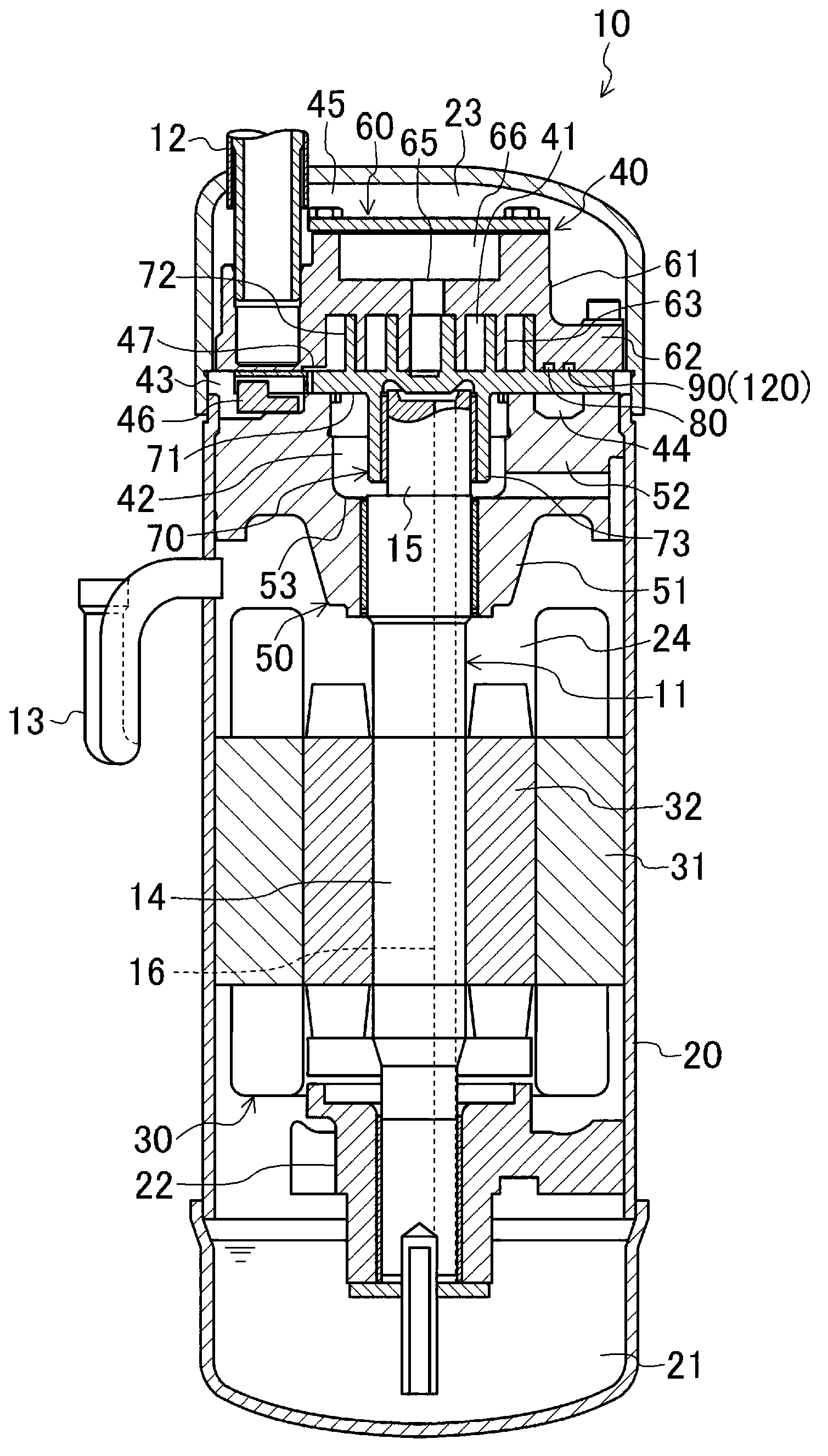
[0060] The scroll compressor 10 according to the first embodiment is connected to a refrigerant circuit of a refrigeration device. That is, the refrigeration device performs a vapor compression refrigeration cycle by circulating refrigerant compressed in the scroll compressor 10 in the refrigerant circuit.
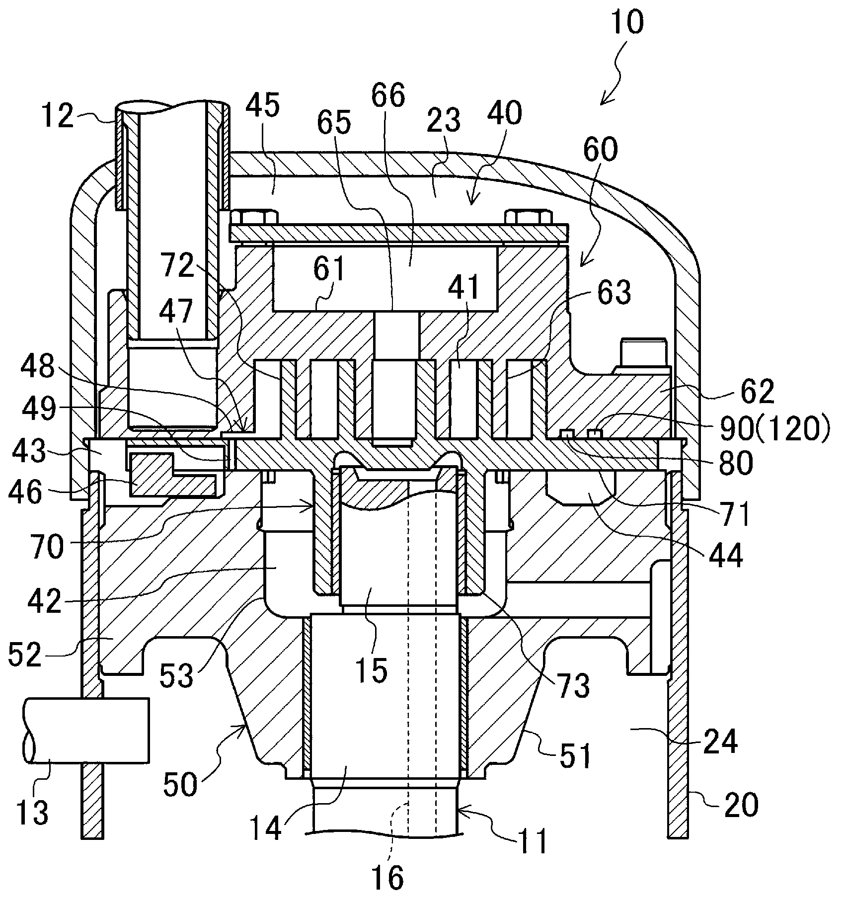
[0061] Such as figure 1 and figure 2 As shown, the scroll compressor 10 includes a casing 20 and a motor 30 and a compression mechanism 40 installed in the casing 20 . The casing 20 is formed in a high cylindrical shape, and constitutes a closed dome.
[0062] The motor 30 constitutes a drive mechanism that rotates the drive shaft 11 to drive the compression mechanism 40 . The motor 30 includes a stator 31 fixed on the casing 20 and a rotor 32 arranged inside the stator 31 . The drive shaft 11 is inserted into the rotor 32 to fix the rotor 32 on the drive shaft 11 .
[0063]The bottom of the casing 20 is configured as an oil storage portion 21 for storing lubricating...
no. 2 approach
[0105] A scroll compressor 10 according to the second embodiment differs from the first embodiment described above in the configuration of the adjustment mechanism. Specifically, in Figure 6 ~ Figure 9 In the adjustment mechanism of the second embodiment shown, an intermediate pressure groove 96 is formed on the outer peripheral side of the high pressure side oil groove 80 . The medium-pressure groove 96 has an open groove 97 extending radially outward in addition to the small-diameter groove 91 and the large-diameter groove 92 as in the first embodiment described above. The open groove 97 communicates with the other end of the large-diameter groove 92 and opens toward the end plate 71 side of the orbiting scroll 70 . In the second embodiment, the outer peripheral end portion of the end plate 71 of the movable scroll 70 constitutes the closing portion 71 a that moves to open and close the opening groove 97 .
[0106] In the second embodiment, the intermediate pressure porti...
no. 3 approach
[0111] A scroll compressor 10 according to the third embodiment differs from the aforementioned first and second embodiments in the structure of the adjustment mechanism. Specifically, in Figure 10 ~ Figure 13 In the adjustment mechanism of the third embodiment shown, the through hole 98 extends in the axial direction on the end plate 71 of the movable scroll 70 . The through hole 98 is formed at a position close to the radially outer side of the end plate 71 and faces the lower surface (sliding surface) of the outer edge portion 62 of the fixed scroll 60 . The through hole 98 rotates eccentrically with the movable scroll 70 . Here, the medium pressure groove 96 forming the communication groove is located on the locus t of the eccentric rotation of the through hole 98 .
[0112]A dynamic side pressure portion 44 constituting a part of the intermediate pressure portion 43 is formed below the through hole 98 . The dynamic-side pressure unit 44 is configured to form a low-pre...
PUM
 Abstract
Description
Claims
Application Information
 - R&D
- Intellectual Property
- Life Sciences
- Materials
- Tech Scout
- Unparalleled Data Quality
- Higher Quality Content
- 60% Fewer Hallucinations
Browse by: Latest US Patents, China's latest patents, Technical Efficacy Thesaurus, Application Domain, Technology Topic, Popular Technical Reports.
© 2025 PatSnap. All rights reserved.Legal|Privacy policy|Modern Slavery Act Transparency Statement|Sitemap|About US| Contact US: help@patsnap.com


