
Cushion block assembly structure for jacking structure and jacking implementation method of cushion block assembly structure

A technology for structures and pads, which is applied to the assembly structure of pads for structure jacking and its jacking implementation field, can solve the problems of difficulty in transporting and installing pads, limited on-site operating space for large bridges, and bulkiness, etc. The method is simple, convenient and reliable, overcomes the difficulty of production, and has good construction safety effects.

Active Publication Date: 2013-07-10
SHANGHAI URBAN CONSTR DESIGN RES INST GRP CO LTD +1
View PDF9 Cites 3 Cited by
  • Summary
  • Abstract
  • Description
  • Claims
  • Application Information

AI Technical Summary

Problems solved by technology

Although there are blocks that are divided into four sides as prototypes, they are still bulky and easy to deform due to their large size and weight, and it is difficult to control the processing quality. The pads may be deformed under pressure, resulting in an increase in the gap between the joints; for the permanent pads that will be part of the pier in the future, the gaps will have an adverse effect on the durability of the structure; or because there is no implicated effect between the pads, it may cause Uneven force on the jack, uneven force or sliding of some pads
[0003] At present, for the jacking of large bridges, due to the self-heavy structure, more jacks are needed to provide jacking force. It is very difficult to install pads, especially the large overall pads may be deformed in any link during the production, transportation, and hoisting process, resulting in unusable construction safety or quality

Method used


Image

  • Cushion block assembly structure for jacking structure and jacking implementation method of cushion block assembly structure
  • Cushion block assembly structure for jacking structure and jacking implementation method of cushion block assembly structure
  • Cushion block assembly structure for jacking structure and jacking implementation method of cushion block assembly structure

Examples


Embodiment 1

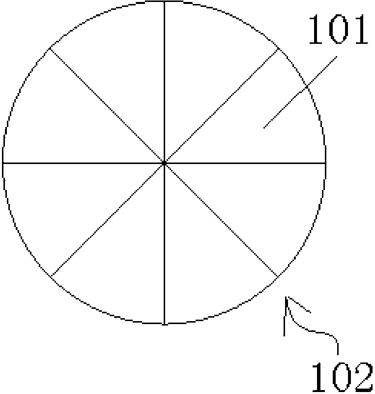
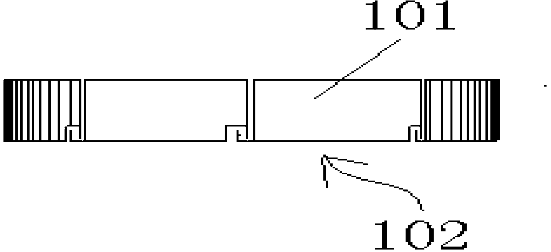
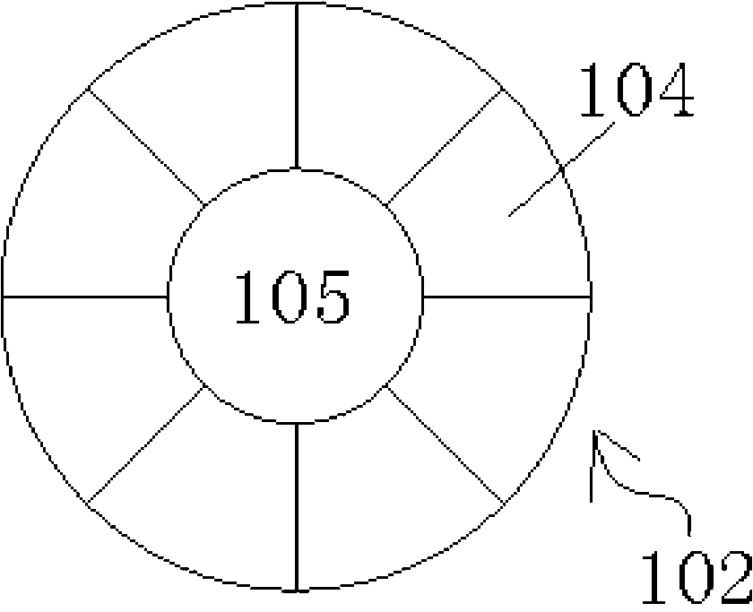
[0037] As shown in the figure, this embodiment proposes a pad assembly structure for structure jacking, including: a pad layer formed by assembling a number of special-shaped pads, and a number of pad layers are stacked vertically to form the lifting structure of the structure. Assemble the structure with pads; the special-shaped pad includes an enclosure plate for enclosing and constructing the shape of the special-shaped pad, the enclosure plate is filled with concrete, and the splicing surface of the enclosure plate is provided with a tongue and groove, A groove-and-groove connection is provided between adjacent special-shaped pads on the same pad layer.

[0038] As a further specific implementation of this embodiment, tunnels for penetrating prestressed tendons are pre-embedded in the pad layer, and prestressed tendons for enhancing the tightness between the special-shaped pads are arranged in the tunnels. The upper and lower ends of the enclosure plate are arranged with r...

Embodiment approach

[0040] The jacking implementation method of the structure jacking pad assembly structure of the present embodiment comprises the following steps:

[0041] Step 1: Assembling several of the special-shaped pads into a pad layer suitable for the cross-section of the installation pier column; wherein, the adjacent special-shaped pads are tightly lapped and fixed through the tongue and groove between the enclosure plates position, and the pre-stressed tendons are stretched and anchored in the channels pre-embedded in the pads, so as to realize the pre-compression between the pads.

[0042] Step 2: superimposing the spacer layer on the jacking installation surface of the installation pier to complete the lifting of the installation pier.

[0043] As a further specific implementation of this embodiment, after step 2 is completed, it also includes: if the section of the assembled pad layer is smaller than the section of the original pier column, when it needs to be determined that the...

Embodiment 2

[0052] Figure 2a It is the attached view of the assembled structure of the cushion blocks for structure jacking in the second embodiment. Figure 2b It is the elevation view of the assembled structure of the cushion block used for lifting the structure of the second embodiment. In order to better adapt to the non-circular cross-section of the installation pier column, the difference from the first embodiment is that the structure jacking pad assembly structure of the present embodiment The special-shaped pads include: Figure 2a The L-shaped spacer 201 and the T-shaped spacer 202 are matched with each other, and the L-shaped spacer 201 and the T-shaped spacer 202 are interlocked and assembled to form a spacer layer 203 with a rectangular cross-section. Specifically, two L-shaped spacers 201 and one T-shaped spacer 202 are buckled together, and the L-shaped spacer 201 is fastened to the left and right sides of the T-shaped spacer 202 .

[0053] In addition, the channel 204 p...


PUM


Abstract

The invention discloses a cushion block assembly structure for jacking a structure and a jacking implementation method of the cushion block assembly structure. The assembly structure comprises cushion block layers formed by assembling a plurality of special-shaped cushion blocks, and a plurality of the cushion block layers are longitudinally superimposed to form the cushion block assembly structure for jacking the structure. The special-shaped cushion blocks comprise enclosing plates used for enclosing to form the shape of the special-shaped cushion blocks, concrete is filled in the enclosing plates, rabbets are arranged on assembly surfaces of the enclosing plates, a rabbet type connection is arranged between adjacent special-shaped cushion blocks positioned on the same cushion block layer. When the cushion block assembly structure is implemented, the plurality of special-shaped cushion blocks are assembled to form the cushion block layers matched with sections of installation pier columns, and then the cushion block layers are superimposed to jacking installation surfaces of the installation pier columns to complete jacking to the installation pier columns. The cushion block assembly structure has high manufacture precision and high cushion block assembly structure and is convenient to transport and install. By utilizing the cushion block assembly structure, the use safety and the late durability can be ensured.

Description

technical field [0001] The invention relates to the technical field of modular auxiliary devices for construction engineering, in particular to a pad assembly structure for jacking up a structure and a jacking implementation method thereof. Background technique [0002] Present bridge jacking pads can be roughly divided into several types such as wooden wedge pads, finishing steel pipe pads and prefabricated reinforced concrete pads. Although the wooden wedge block is easy to make and light in weight, it has low strength and large deformation, so it is not suitable for heavy load jacking environment; the machining accuracy of the finished steel pipe block is easy to control, but the bearing capacity is relatively low and the plane close-packed arrangement is harmful to the environment. The construction space requirements are relatively high; the integral prefabricated reinforced concrete block has high strength, but the disadvantage is that the manufacturing accuracy is not ...

Claims


Application Information

Patent Timeline
Patent Type & Authority Applications(China)
IPC IPC(8): E01D22/00
Inventor 吴培峰闫兴非李方元
Owner SHANGHAI URBAN CONSTR DESIGN RES INST GRP CO LTD
Learn More