Engine exhaust manifold assembly

An exhaust manifold and engine technology, which is applied to engine components, machines/engines, exhaust devices, etc., can solve problems such as failure to meet emission requirements, failure to meet emission standards, and low temperature of exhaust gas, and achieve uniform exhaust gas mixing. , The effect of good engine power and low exhaust back pressure

Inactive Publication Date: 2013-07-10
力帆科技(集团)股份有限公司
View PDF9 Cites 2 Cited by
  • Summary
  • Abstract
  • Description
  • Claims
  • Application Information

AI Technical Summary

Problems solved by technology

To a certain extent, this structure solves the problem that the three-way catalytic converter cannot meet the emission requirements due to the low temperature of the exhaust gas during cold start, reduces the e

Method used


Image

  • Engine exhaust manifold assembly
  • Engine exhaust manifold assembly
  • Engine exhaust manifold assembly

Examples


Embodiment Construction

[0017] The present invention will be further described below in conjunction with drawings and embodiments.

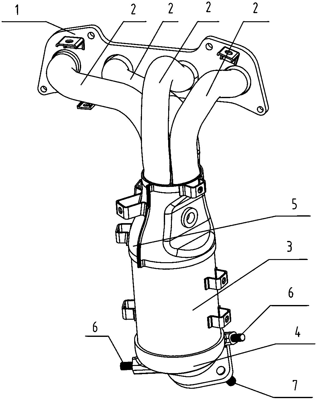
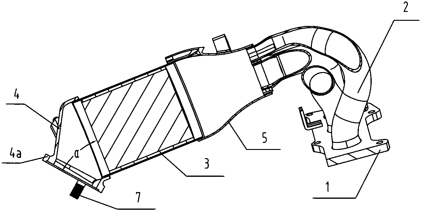
[0018] Figure 1, figure 2 The engine exhaust manifold assembly shown is composed of intake flange 1, multiple exhaust manifolds 2 arranged side by side, three-way catalytic converter 3, outlet flange 4, horn-shaped transition pipe 5, support screws 6 and Connecting screw 7 forms.

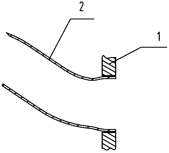
[0019] to combine image 3 As shown, each exhaust manifold 2 is made of bent stainless steel pipes with basically the same length. The front ports of the exhaust manifolds 2 are flared and installed on the intake flange 1 at intervals. The three-way catalytic converter 3 is cylindrical. After the rear ends of the exhaust manifolds 2 are brought together, they are connected to the front end of the three-way catalytic converter 3 through a horn-shaped transition pipe 5. The inner diameter of the horn-shaped transition pipe 5 is determined by the front end It gradually increases toward the re...


PUM


Abstract

The invention discloses an engine exhaust manifold assembly. The front end mouth portion of each exhaust manifold is extended and is mounted at intervals on an air inlet flange, a three-way catalyst is cylindrical, the back end of each exhaust manifold is gathered together and connected with the front end of the three-way catalyst through a horn-shaped transition tube, the inner diameter of the horn-shaped transition tube is gradually increased from the front end to the back end, the air inlet flange is a casting part and is sleeved at the back end of the three-way catalyst, an included angle alpha of 20-80 degrees is formed between the front end face and the back end face of the air inlet flange, the inner diameter of the air inlet flange is gradually decreased from the front end to the back end, the back end of the three-way catalyst is inserted into the front end mouth portion of the air inlet flange and is welded with the air inlet flange, and the back end mouth portion of the air inlet flange extends outwards to form a flange mounting plate. The engine exhaust manifold assembly has the advantages of simple structure, low air discharging back pressure, good engine dynamic property, small heat loss, high cold starting property and the like, and requirements of national five emission standards can be met.

Description

technical field [0001] The invention relates to an engine exhaust system, in particular to an engine exhaust manifold assembly structure. Background technique [0002] The engine exhaust manifold is one of the key components of the engine exhaust system. Its working condition is directly related to the working reliability and durability of the engine, and at the same time directly affects the emission performance of the engine. With the continuous improvement of people's awareness of environmental protection, in order to avoid the threat of severe weather such as smog to human health, the newly issued National V emission standards put forward higher requirements for engine emissions, and as the exhaust system of the engine The performance requirements of the key component - the exhaust manifold assembly are getting higher and higher. [0003] The State Intellectual Property Bureau discloses an engine exhaust manifold assembly with a three-way catalytic converter (patent num...

Claims


Application Information

Patent Timeline
IPC IPC(8): F01N13/10F01N3/28
Inventor 黄寅桂龙华唐素芳
Owner 力帆科技(集团)股份有限公司
Why Eureka
Try Eureka