
Method and device of sound velocity measurement

A sound speed and sound wave technology, applied in the field of sound speed measurement, can solve the problems of complicated operation, inability to realize real-time online measurement, poor measurement accuracy, etc., and achieve the effects of accurate measurement results, simple structure and low cost.

Active Publication Date: 2013-07-10
SHANXI UNIV
View PDF2 Cites 11 Cited by
  • Summary
  • Abstract
  • Description
  • Claims
  • Application Information

AI Technical Summary

Problems solved by technology

[0004] The present invention provides a method and device for measuring sound velocity in order to solve the technical problems of current existing sound velocity measuring instruments and methods, such as cumbersome operation, poor measurement accuracy, manual intervention and inability to realize real-time online measurement

Method used


Image

  • Method and device of sound velocity measurement
  • Method and device of sound velocity measurement
  • Method and device of sound velocity measurement

Examples


Embodiment 1

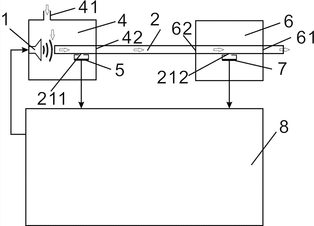
[0028] Embodiment 1 The acoustic wave guide adopts a linear guide, and the device used to obtain the phase difference information of the sound wave between the second small hole and the first small hole is a lock-in amplifier 82 .

Embodiment 2

[0029] Embodiment 2 The acoustic wave guide adopts a linear guide, and the devices used to obtain the phase difference information of the acoustic wave between the second small hole and the first small hole are three phase detectors.

Embodiment 3

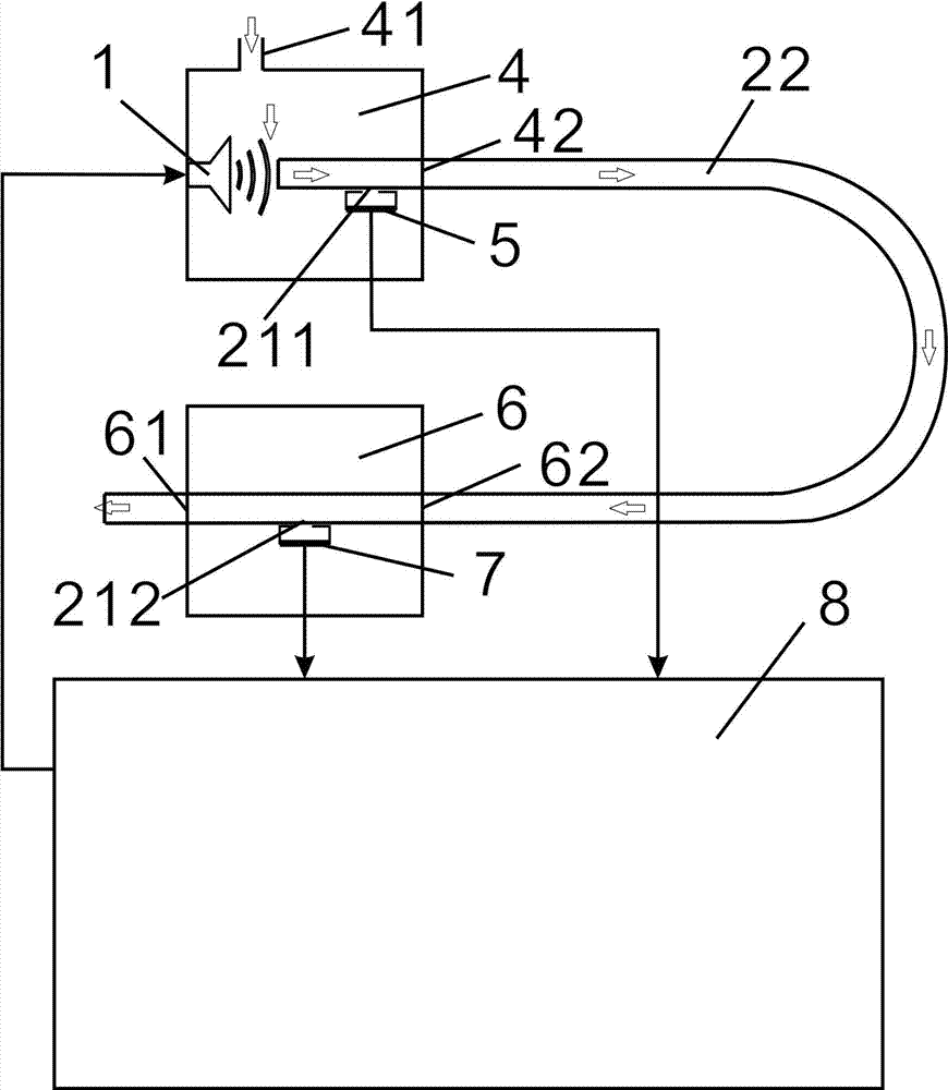
[0030] Embodiment 3 The acoustic waveguide adopts a U-shaped acoustic waveguide 22 , and the device for obtaining the phase difference information of the acoustic wave between the second small hole and the first small hole is a lock-in amplifier 82 .


PUM


Abstract

The invention relates to a measurement technology of sound velocity, in particular to a method and a device of sound velocity measurement. The method and the device of the sound velocity measurement are used for solving the technical problems that an existing sound velocity measurement device and an existing sound velocity measurement method are complex in operation, poor in measurement accuracy and the like. The method of the sound velocity measurement comprises the following steps of (a) inputting a sine sound wave with a frequency of fi through the front end of a sound wave guide tube, wherein the sound wave guide tube is filled with specific gas, and the length of the sound wave guide tube is 1, and recording a phase difference phi i, between the rear end and the front end of the sound wave guide tube, of the sine sound wave; (b) changing the frequency of the sine sound wave, and measuring at least one group of values from the fi to the phi i; and (c) calculating the value of 2pi l / vs using a linear fitting method according to the obtained values from the fi to the phi i, and obtaining a sound level vs. The device of the sound velocity measurement comprises a first air chamber and a second air chamber, and further comprises the sound wave guide tube. The front end of the sound wave guide tube penetrates through a first passing hole to enter the first air chamber. The rear end of the sound wave guide tube passes a third passing hole and a second passing hole, and penetrates through the second air chamber. The method and the device of the sound velocity measurement achieve high automation of measurement, and are simple in structure and low in cost.

Description

technical field [0001] The invention relates to the measurement technology of sound velocity, in particular to a method and device for measuring sound velocity. Background technique [0002] The sound velocity in gas has a great relationship with the composition of the gas. For example, the sound velocity is 340m / s under air, but it is as high as 972m / s under He. The gas sensor based on photoacoustic spectroscopy is based on the measurement of the weak sound released after the gas absorbs light. Usually photoacoustic spectroscopy uses a sound resonant cavity, and the half-wave wavelength of the weak sound signal to be measured is the same as the sound The length of the resonant cavity is equal, so the sound wave can form a standing wave in the cavity, which further enhances the detected weak sound wave. But under complex gas composition, the change of sound velocity can lead to drastic change of sound wave wavelength, so that the length of the sound resonant cavity does not...

Claims


Application Information

Patent Timeline
Patent Type & Authority Applications(China)
IPC IPC(8): G01H5/00
Inventor 董磊贾锁堂尹王保
Owner SHANXI UNIV
Learn More