A flow battery shutdown protection method and a flow battery system

A flow battery, shutdown protection technology, applied in fuel cells, regenerative fuel cells, circuits, etc., can solve problems such as high load life performance and life requirements, affecting stack life, not experiencing dynamic operation, etc., to achieve battery life. The effect of long time, low investment and slow capacity decay

Active Publication Date: 2016-01-13
大连融科储能装备有限公司
View PDF10 Cites 0 Cited by
  • Summary
  • Abstract
  • Description
  • Claims
  • Application Information

AI Technical Summary

Problems solved by technology

However, this method has higher requirements on the load voltage level, and different voltage levels need to use different loads. In addition, the discharge load needs to undergo frequent charge and discharge cycles, which requires high load life performance and life; on the other hand, Although the battery has performed a discharge operation, the electrolyte in the stack does not undergo dynamic operation during the discharge process, and a large amount of heat generated during the discharge process cannot be taken away, which affects the service life of the stack

Method used


Image

  • A flow battery shutdown protection method and a flow battery system

Examples


Embodiment 1

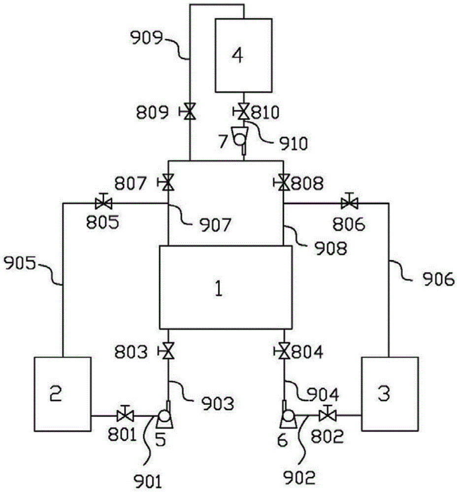
[0028] A liquid flow battery system, the battery system includes a stack 1, a positive electrolyte storage tank 2, a negative electrolyte storage tank 3, a positive electrolyte delivery pump 5, a negative electrolyte delivery pump 6, a mixed solution storage tank 4 and Mixed solution delivery pump 7.

[0029] The stack 1 is connected to the positive electrode electrolyte delivery pump 5 and the negative electrode electrolyte delivery pump 6 respectively through the pipeline III903 and the pipeline IV904, and the valve III803 and the valve IV804 are respectively set on the pipeline III903 and the pipeline IV904; the positive electrode electrolyte delivery pump 5 and the negative electrode electrolytic The liquid delivery pump 6 is connected to the positive electrode electrolyte storage tank 2 and the negative electrode electrolyte storage tank 3 through the pipeline I901 and the pipeline II902 respectively. The positive electrode electrolyte storage tank 2 and the negative elec...

Embodiment 2

[0033] Device and mode of operation are the same as embodiment 1

[0034] When the battery power is 10kw, the solution in the battery is 100L, the SOC state is 30%, the voltage across the battery is 47V, and 30L of solution is stored in the mixed solution storage tank 4 . The voltage disappears after discharge.

Embodiment 3

[0036] Device and mode of operation are the same as embodiment 1

[0037] After the stack is assembled into a battery system with a success rate of 100kw, the solution in the storage tank in the battery system is 1000L at this time. When the SOC state of the battery system is 50%, the voltage at both ends of the battery is 320V. At this time, it needs to be stored in the storage tank 4 500L solution. After the battery system was discharged, the voltage disappeared after injecting 500L of mixed solution into the system.


PUM


Abstract

The invention relates to a liquid flow battery halt protection method and a liquid flow battery system with a halt protection function, and belongs to the field of liquid flow batteries. The liquid flow battery halt protection method is that the positive polo electrolyte and the negative pole electrolyte in the galvanic pile after the liquid flow battery system is halted are mixed in at least one container outside the galvanic pile, then transported back to the galvanic pile of the liquid flow battery system. The method provided by the invention can quickly release the electric energy in the battery, thus the life of the battery is longer, the fading of the capacity is slower, and long-time stable operation of the system is ensured.

Description

technical field [0001] The invention relates to a liquid flow battery shutdown protection method and a liquid flow battery system with a shutdown protection function, belonging to the field of liquid flow batteries. Background technique [0002] Electric energy is difficult to store and indispensable. Its production must meet the demand for electricity at any time. Therefore, people have been looking for economical and feasible energy storage technologies to solve the contradiction between supply and demand and decouple the production of electric energy from demand. In addition, electric energy storage plays an important role in electric energy management, grid auxiliary services, voltage control, renewable energy utilization, and large-scale uninterruptible power supplies. If combined with large-scale thermal power generation, it can reduce the peak capacity of power stations, reduce power generation costs, and reduce pollution. If it is combined with renewable energy such ...

Claims


Application Information

Patent Timeline
Patent Type & Authority Patents(China)
IPC IPC(8): H01M8/04228H01M8/18
CPCY02E60/50
Inventor 杨振坤张华民许晓波高素军张宇焦德贺
Owner 大连融科储能装备有限公司
Why Eureka
Try Eureka