Rare earth doping optical fiber light source light path structure
A technology of rare earth doping and optical fiber light source, which is applied in the field of optical fiber communication and optical fiber sensing, and can solve the problems of increasing the cost of raw materials
- Summary
- Abstract
- Description
- Claims
- Application Information
AI Technical Summary
Problems solved by technology
Method used
Image
Examples
Embodiment 1
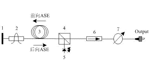
[0039] Technical scheme 1 that the present invention adopts, as figure 1 Shown: including Faraday rotation mirror 1, optical filter 2, erbium-doped fiber 3, pump signal combiner 4, pump laser 5, isolator 6, attenuator 7; optical filter 2 is respectively connected to the Faraday rotation reflector Mirror 1 and erbium-doped fiber 3, the other end of erbium-doped fiber 3 is connected to the common end of pump signal combiner 4, the pump end of pump signal combiner 4 is connected to pump laser 5, and the pump signal combiner 4 is transmitted Connect the input end of the isolator 6, connect the output end of the isolator 6 to the input end of the attenuator 7, and connect the other end of the attenuator 7 to the output pigtail. The working process of the optical path structure of the erbium-doped fiber light source in this embodiment is specifically as follows: under the excitation of the pump light, the forward and backward propagating ASEs are simultaneously generated in the erbi...
Embodiment 2
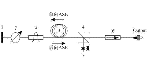
[0043] The technical scheme 2 that the present invention adopts, as figure 2Shown: including Faraday rotating mirror 1, attenuator 7, optical filter 2, erbium-doped fiber 3, pump signal combiner 4, pump laser 5, isolator 6; Faraday rotating mirror 1 is connected to attenuator 7 , the optical filter 2 is respectively connected to the other end of the attenuator 7 and the erbium-doped optical fiber 3, the other end of the erbium-doped optical fiber 3 is connected to the common end of the pump signal multiplexer 4, and the pump end of the pump signal multiplexer 4 is connected to the pump laser 5. The transmission end of the pump signal combiner 4 is connected to the input end of the isolator 6, and the output end of the isolator 6 is connected to the output pigtail. The working process of the light path structure of the erbium-doped fiber light source in this embodiment is as follows: under the excitation of the pump light, forward and backward ASEs are simultaneously generated...
Embodiment 3
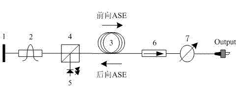
[0048] Technical scheme 3 that the present invention adopts, as image 3 Shown: including Faraday rotation mirror 1, optical filter 2, pump signal combiner 4, pump laser 5, erbium-doped optical fiber 3, isolator 6, attenuator 7; optical filter 2 is respectively connected to Faraday rotation reflector The mirror 1 and the transmission end of the pump signal multiplexer 4, the pump end of the pump signal multiplexer 4 is connected to the pump laser 5, and the erbium-doped optical fiber 3 is respectively connected to the common end of the pump signal multiplexer 4 and the input end of the isolator 6 , the output end of the isolator 6 is connected to the attenuator 7, and the output end of the attenuator 7 is connected to the output pigtail. The working process of the light path structure of the erbium-doped fiber light source in this embodiment is as follows: under the excitation of the pump light, forward and backward ASEs are simultaneously generated in the erbium-doped fiber, ...
PUM
 Abstract
Description
Claims
Application Information
 - R&D
- Intellectual Property
- Life Sciences
- Materials
- Tech Scout
- Unparalleled Data Quality
- Higher Quality Content
- 60% Fewer Hallucinations
Browse by: Latest US Patents, China's latest patents, Technical Efficacy Thesaurus, Application Domain, Technology Topic, Popular Technical Reports.
© 2025 PatSnap. All rights reserved.Legal|Privacy policy|Modern Slavery Act Transparency Statement|Sitemap|About US| Contact US: help@patsnap.com


