Mechanical and electrical integration linear driving device

A linear drive, electromechanical technology, applied in the direction of electromechanical devices, electric components, electrical components, etc., can solve the problems of high processing costs and procurement costs, reduced transmission accuracy of linear drive devices, complex equipment maintenance, etc., to reduce processing Control nodes, reduce assembly workload and process difficulty, and improve the effect of IP level

Active Publication Date: 2013-07-10
成都瑞迪智驱科技股份有限公司
View PDF6 Cites 13 Cited by
  • Summary
  • Abstract
  • Description
  • Claims
  • Application Information

AI Technical Summary

Problems solved by technology

[0009] 2. Based on the relatively complex structure of the linear drive device mentioned in Article 1, the entire transmission route is relatively complicated. If the accuracy of a certain part cannot be guaranteed, the transmission accuracy of the entire linear drive device will be greatly reduced. Therefore, for each The precision of transmission parts has put forward high requirements
[0010] 3. Based on the structure of the linear drive device described in Article 1, there are many parts and complex assembly, which means that the processing cost and procurement cost remain high. This is also the case with the general planetary roller screw type linear drive device. But the main reason why it has not been able to be used in large quantities
[0011] 4. Due to the complex structure of the equipment and the high precision of the parts, the maintenance of the equipment is also very complicated

Method used


Image

  • Mechanical and electrical integration linear driving device
  • Mechanical and electrical integration linear driving device
  • Mechanical and electrical integration linear driving device

Examples


Embodiment Construction

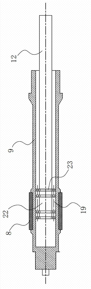
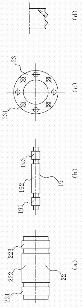
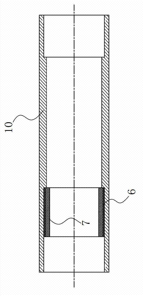
[0034] Such as Figures 1 to 4 The shown linear drive device includes an output shaft 12 and a lead screw pair, the output shaft 12 and the lead screw 22 of the lead screw pair are fixed through threaded connection, and the described device includes a cylinder body 10, and the stator assembly is fixed inside the cylinder body 10; The lead screw nut 9 of the lead screw pair is long cylindrical, and the rotor assembly matched with the stator assembly is fixed outside the lead screw nut 9 . As for ensuring the operation of the lead screw pair, it is necessary to fix the lead screw nut 9 of the lead screw pair with a bearing, and at the same time position the output shaft 12 that needs axial movement, then there are many embodiments that can be realized. Usually: the lead screw nut 9 and the output shaft 12 of the lead screw pair are respectively positioned through bearings; Rotational motion, output shaft 12 can do linear motion under the drive of lead screw 22 and get final pro...


PUM


Abstract

The invention relates to a linear driving device and aims to provide a mechanical and electrical integration linear driving device which is reliable in performance, simple in structure, convenient to assemble, and cost-saving. The mechanical and electrical integration linear driving device comprises an output shaft, a lead screw pair and a cylinder body, wherein the output shaft is connected with the lead screw pair, a stator module is fixed inside the cylinder body, a lead screw nut of the lead screw pair is of a long cylinder shape, and a rotor module which is matched with the stator module is fixed outside the lead screw nut. The stator module of a motor is designed on the lead screw nut of the lead screw pair, namely the motor stator module and the lead screw nut are regarded as a whole to form a stator of the motor, the motor stator is placed inside the linear driving device, namely the motor stator module and the cylinder body are regarded as a whole to form a rotor of the motor, and therefore mechanical and electrical integration of the linear driving device is achieved. The mechanical and electrical integration linear driving device has the advantages of being reliable in performance, simple in structure, convenient to assemble and cost-saving.

Description

technical field [0001] The invention relates to a linear drive device, in particular to a linear drive device using a lead screw pair. Background technique [0002] With the steady development of my country's industry, there are more and more occasions where linear drive devices are used to push, pull, and lift objects, and the application fields of linear drive devices are also constantly expanding. From the automotive industry, to mining machinery, aerospace, medical equipment, industrial control, CNC machine tools, to solar power generation industry, linear drive devices can be seen everywhere. But at the same time, with the deepening of the application industry, the precision requirements for linear drive devices are getting higher and higher, such as machine tool equipment and aerospace industries, not only require linear drive devices to have high transmission accuracy and high transmission efficiency, but also It is required to have the characteristics of long life a...

Claims


Application Information

Patent Timeline
Patent Type & Authority Applications(China)
IPC IPC(8): H02K7/06
Inventor 胥勋泽周小平肖平黎启华唐国华雷田东何龙卢晓蓉
Owner 成都瑞迪智驱科技股份有限公司
Why Eureka
Try Eureka