Rotary cutting machine

A technology of rotary cutting machine and rotary cutter, which is applied to metal processing machinery parts, clamping, supporting and other directions, can solve the problems of poor performance, slow cutting speed, low efficiency, etc. cost effect

Inactive Publication Date: 2013-07-17
帅家园 +1
View PDF6 Cites 20 Cited by
  • Summary
  • Abstract
  • Description
  • Claims
  • Application Information

AI Technical Summary

Problems solved by technology

The cutting surface of the band saw is linear, which is formed by a plurality of saw blades arranged linearly. The material is fixed during work, and the cutting surface is driven by the driving mechanism to make a linear reciprocating motion on the material to cut the material. This band saw Not only the cutting speed is slow, but once a saw blade breaks, the band saw cannot work normally and the performance is poor
[0006] 2. Ordinary circular saw
However, the length, diameter, weight, uniformity and other factors of the material have become the bottleneck restricting its speed. When the length of the material is too long, the diameter is too large, the weight is too large, and the weight is eccentric, if it rotates at a high speed, it will cause severe vibration. Only 500-600 rpm, especially when cutting longer and thicker materials, in order to ensure smooth cutting, the material speed can only be lower, so the disadvantages of slow cutting speed and low efficiency of this passive cutting machine are particularly obvious

Method used


Image

  • Rotary cutting machine
  • Rotary cutting machine
  • Rotary cutting machine

Examples


Embodiment Construction

[0041] The present invention will be further described below with reference to the accompanying drawings and specific embodiments.

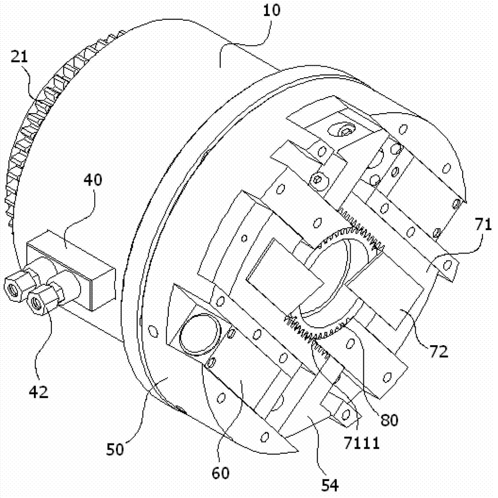
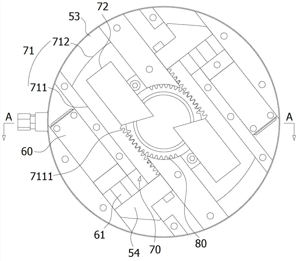
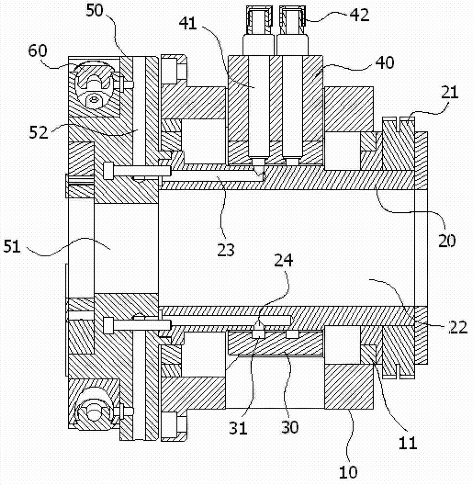
[0042] Please refer to Figures 1 to 3 As shown, it has shown the concrete structure of preferred embodiment of the present invention, rotary cutting machine, comprises main shaft outer cover 10, main shaft rotor 20, slip ring 30, rotating disk 50, oil cylinder 60 and at least one rotary cutter 70, wherein:

[0043] The main shaft cover 10 has an inner cavity, the main shaft rotor 20 is installed in the inner cavity of the main shaft cover 10, the main shaft cover 10 is provided with an opening, the main shaft rotor 20 is covered with a bearing 11 fixed on the main shaft cover 10, the main shaft rotor 20 has a first hollow passage 22 extending from its rear end to its front end, and a second oil passage 23 is arranged in the main shaft rotor 20, and a hole 24 communicating with the second oil passage 23 is opened on the main shaft rotor 20; The ...


PUM


Abstract

The invention discloses a rotary cutting machine. The rotary cutting machine comprises a spindle jacket with an inner cavity, a spindle rotor, a slip ring, a rotary disc, oil cylinders and rotary cutters, wherein the spindle rotor is mounted in the inner cavity and provided with a first hollow channel extending from the rear end to the front end, a gap is reserved between the spindle rotor and the spindle jacket, and second oil ways are arranged in the spindle rotor, the slip ring is sleeved on the periphery of the spindle rotor and provided with a groove which extends circumferentially and communicated with the second oil ways, gaps are reserved between the slip ring and the spindle rotor as well as between the slip ring and the spindle jacket, a press block is connected with the slip ring via bolts, first oil ways are arranged in hollow interiors of the bolts, oil nozzles are mounted at the upper ends of the bolts, the first oil ways are respectively communicated with the oil nozzles and the groove, the rotary disc is provided with third oil ways communicated with the second oil ways, the oil cylinders are mounted on the rotary disc, oil ports of the oil cylinders are communicated with the third oil ways, and the rotary cutters comprise supports and cutting tools. During use, the spindle rotor of the rotary cutting machine is supported by hydraulic oil to be free of contact with the spindle jacket and the slip ring, so that friction force is reduced, rotating speed is increased, cutting speed is high, and efficiency is high.

Description

[0001] technical field [0002] The invention relates to a material cutting device, in particular to a rotary cutter. [0003] Background technique [0004] In the field of material cutting, there are currently many types of cutting equipment on the market for cutting materials into segments, such as cutting hollow pipes into tubes, and cutting solid rods into rods. Specifically, the existing cutting The main types of equipment are as follows: [0005] 1. Band saw. The cutting surface of the band saw is linear, which is formed by a plurality of saw blades arranged linearly. The material is fixed during work, and the cutting surface is driven by the driving mechanism to make a linear reciprocating motion on the material to cut the material. This band saw Not only is the cutting speed slow, but once a certain saw blade breaks, the band saw cannot work normally and has poor performance. [0006] 2. Ordinary circular saw. There is a circle of hacksaw blades distributed on t...

Claims


Application Information

Patent Timeline
IPC IPC(8): B23D79/00B23Q3/00B23Q11/12
CPCB26D3/16B23B3/26B23B5/08B23B29/03489B23B2270/025
Inventor 帅家园陈名乔
Owner 帅家园
Why Eureka
Try Eureka