Pneumatic ejecting mechanism of welding jig

A welding fixture and top piece technology, applied in welding equipment, auxiliary welding equipment, welding/cutting auxiliary equipment, etc., can solve the problems of low production efficiency, long time consumption, difficulty in taking out, etc. The effect of improving the efficiency of welding work

Inactive Publication Date: 2013-07-17
WUXI ZHONGJIE VIBRATION ISOLATORS
View PDF5 Cites 7 Cited by
  • Summary
  • Abstract
  • Description
  • Claims
  • Application Information

AI Technical Summary

Problems solved by technology

In the past, when welding cylinder parts, the welded parts were usually taken out by hand. Because the temperature of the welded parts is high, and the cylinder wall is closely matched with the welding fixture, it is difficult to take out and takes a long time. Large-scale production caused a lot of waste of time and low production efficiency

Method used


Image

  • Pneumatic ejecting mechanism of welding jig
  • Pneumatic ejecting mechanism of welding jig

Examples


Embodiment Construction

[0009] The present invention will be further described below in conjunction with specific drawings and embodiments.

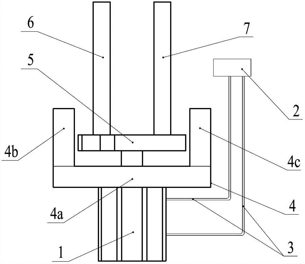
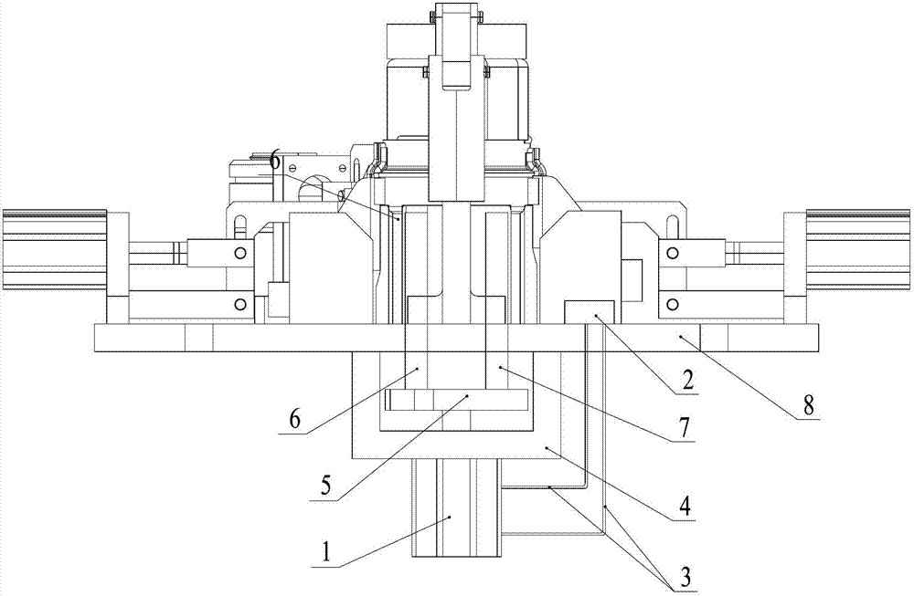
[0010] As shown in the figure: the pneumatic ejector mechanism of the welding fixture in the embodiment is mainly composed of a cylinder 1, a mechanical valve 2, an air pipe 3, a bracket 4, an ejector plate 5, a first ejector rod 6 and a second ejector rod 7, The support 4 is fixedly installed on the welding fixture, and the cylinder 1 is fixed on the support 4. The main function of the cylinder 1 is to provide power for the ejector plate 5 to lift up and down; the air inlet and the air outlet of the cylinder 1 pass through the air pipe 3 respectively Connect the mechanical valve 2, the mechanical valve 2 controls the expansion and contraction of the piston rod of the cylinder 1, the piston rod end of the cylinder 1 is connected to the ejector plate 5, and the first ejector rod 6 and the second ejector rod 7 are installed on the ejector plate 5, the bottom plat...


PUM


Abstract

The invention relates to a pneumatic ejecting mechanism of a welding jig. The pneumatic ejecting mechanism is characterized by comprising a cylinder, a mechanical valve, an air tube, a stand, an ejector plate, a first ejector rod and a second ejector rod, wherein the stand is fixedly arranged on the welding jig, the cylinder is fixedly arranged on the stand, an air inlet and an air outlet of the cylinder are respectively connected with the mechanical valve by the air tube, a piston rod of the cylinder is controlled to stretch out and draw back by the mechanical valve, the piston rod end of the cylinder is connected with the ejector plate, the first ejector rod and the second ejector rod are arranged on the ejector plate, allowance holes through which the first ejector rod and the second ejector rod can penetrate are formed in a bottom plate of the welding jig, and the first ejector rod and the second ejector rod can freely move on the corresponding allowance holes. The pneumatic ejecting mechanism is simple, compact and reasonable in structure, welded parts in the welding jig can be ejected out in a pneumatic manner so as to be taken conveniently, the problem of difficulty in taking the welded parts can be eliminated, the time for taking the parts can be greatly shortened, and the welding work efficiency can be improved so as to win the benefits for enterprises.

Description

technical field [0001] The invention relates to a pneumatic ejector mechanism of a welding fixture, specifically a mechanism for ejecting parts welded in a welding fixture in a pneumatic manner, and belongs to the technical field of mechanical equipment. Background technique [0002] Fixtures are tools commonly used in the manufacturing industry to quickly and accurately position and fix processing objects and installation objects. Welding refers to the process of welding workpieces (of the same material or dissimilar materials) through heating or pressure or both, and with or without filling materials, so that the materials of the workpieces can be bonded between atoms to form a permanent connection. During this process, a certain part of the workpiece is rapidly heated and then cooled. The welding zone cannot freely expand and contract due to the constraints of the surrounding workpiece body. After cooling, welding stress and deformation will occur in the weldment. In ord...

Claims


Application Information

Patent Timeline
Patent Type & Authority Applications(China)
IPC IPC(8): B23K37/00
Inventor 魏忠刘耀军
Owner WUXI ZHONGJIE VIBRATION ISOLATORS
Why Eureka
Try Eureka