Device for directly drawing helical circular quartz tube by continuous-melt method and drawing method

A technology of spiral ring and quartz tube, which is applied in the manufacture of tools, glass molding, glass molding, etc., can solve the problems of inconsistent high pressure resistance, irregular spiral ring, uneven pitch, etc., to avoid secondary processing and uniform pitch , the effect of saving energy

Active Publication Date: 2015-06-10
LIANYUNGANG HUAYUAN QUARTZ PROD
View PDF3 Cites 1 Cited by
  • Summary
  • Abstract
  • Description
  • Claims
  • Application Information

AI Technical Summary

Problems solved by technology

The disadvantage of this technology is that secondary processing is required, which requires high energy consumption and long time consumption; and due to the temperature and time of secondary heating, the softening degree of the quartz tube, etc., it is easy to cause irregular spiral rings, uneven spacing, and uneven tube diameters. , Inconsistent high pressure resistance, etc.

Method used


Image

  • Device for directly drawing helical circular quartz tube by continuous-melt method and drawing method

Examples


Embodiment 1

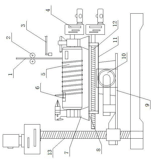
[0017] Embodiment 1, referring to the accompanying drawings, a device for directly drawing a spiral annular quartz tube by continuous melting method, including a rotary winder located below the discharge port of the continuous melting furnace, and the rotary winder is fixed on the support plate through a support frame 7 8, the bottom of the support plate 8 is provided with a left and right movement mechanism 4 that drives the rotary winder to move left and right, and a front and rear movement mechanism 10 is provided at the bottom of the left and right movement mechanism 4, and the lower end of the front and rear movement mechanism 10 is arranged on the lifting mechanism , the rotary winding device includes a rotating cylinder 5, the rotating cylinder 5 is fixed on the rotating shaft, and the rotating shaft is connected with the driving motor through a transmission device, and the rotating cylinder 5 is provided with a quartz tube pressing plate 6; A quartz tube downward tracto...

Embodiment 2

[0021] Embodiment 2, in the device for directly drawing the spiral annular quartz tube by the continuous melting method described in Embodiment 1, the left and right moving mechanism 4 includes a moving frame 11 fixed on the support plate 8, and the moving frame 11 is provided with a left and right moving guide in parallel. Axle and left and right moving screw rod 12, left and right moving screw rod 12 are connected on the mobile frame 11 by nut, and one end of left and right moving screw rod 12 links to each other with driving device.

Embodiment 3

[0022] Embodiment 3, in the device for directly drawing the spiral annular quartz tube by the continuous melting method described in embodiment 2, the left and right moving guide shafts include linear bearings arranged on the moving frame 11, and the linear guide shafts are installed on the linear bearings to prevent the support plate from 8 offset.


PUM

PropertyMeasurementUnit
diameteraaaaaaaaaa
diameteraaaaaaaaaa
diameteraaaaaaaaaa

Abstract

Disclosed are an apparatus for directly drawing a helical annular quartz tube using a continuous smelting method and a method for drawing a helical annular quartz tube using the apparatus. The apparatus comprises a rotating coiler arranged below a material outlet of a continuous smelting furnace, wherein the rotating coiler is fixed onto a support plate via a support frame, a lower part of the support plate is provided with a left / right moving mechanism driving the rotating coiler to move to the left and right, a lower part of the left / right moving mechanism is provided with a front / rear moving mechanism, and a lower end of the front / rear moving mechanism is arranged on a lifting mechanism. The rotating coiler comprises a rotating drum, wherein the rotating drum is fixed on a rotary shaft, the rotary shaft is connected to a driving electric motor via a transmission, and a quartz tube pressing plate is provided on the rotating drum. A quartz tube descent traction machine is provided between the material outlet of the continuous smelting furnace and the rotating coiler, and a quartz tube cutter is provided between the quartz tube descent traction machine and the rotating coiler.

Description

technical field [0001] The invention relates to a device for directly drawing a spiral annular quartz tube by a continuous melting method; the invention also relates to a method for preparing a spiral annular quartz tube by using the aforementioned device. Background technique [0002] At present, the continuous melting method at home and abroad is generally used to straighten the tube by a tube drawing machine, and cut it into different lengths according to the needs of users. If it is to be made into a spiral ring, it needs to be heated twice with hydrogen and oxygen, and then processed by a shaping mold. . The disadvantage of this technology is that secondary processing is required, which requires high energy consumption and long time consumption; and due to the temperature and time of secondary heating, the softening degree of the quartz tube, etc., it is easy to cause irregular spiral rings, uneven spacing, and uneven tube diameters. , Inconsistent high pressure resist...

Claims


Application Information

Patent Timeline
Patent Type & Authority Patents(China)
IPC IPC(8): C03B20/00
CPCC03B23/06C03B17/04
Inventor 王绪东王耀辉
Owner LIANYUNGANG HUAYUAN QUARTZ PROD
Why Eureka
Try Eureka