Combination method and apparatus for laser shock processing of engine blade

A technology of engine blades and laser shock, applied in heat treatment furnaces, heat treatment equipment, furnaces, etc., can solve the problems of reduced processing efficiency, fatigue fracture, large blades, etc., and achieve the effects of avoiding fatigue fracture, improving fatigue life, and improving processing efficiency

Inactive Publication Date: 2013-07-17
BEIJING AERONAUTICAL MFG TECH RES INST +2
View PDF4 Cites 29 Cited by
  • Summary
  • Abstract
  • Description
  • Claims
  • Application Information

AI Technical Summary

Problems solved by technology

[0003] Fatigue fractures of aircraft engine blades generally occur at the edge of the blade. Therefore, laser shock treatment is mainly performed on the edge of the blade, such as figure 1 As shown, the gray area is the laser shock treatment area. Generally, the laser shock treatment uses the same parameters to process this area; the fatigue life of the blade after laser shock treatment is greatly improved, however, the fatigue fracture site is transferred from the edge area to the The transition area between laser shock treatment and non-laser shock treatment; this is because the surface layer of the laser shock treatment area has high residual compressive stress, and the stress change amplitude of the transition area adjacent to the non-shock treatment area is too large, which is easy to cause fatigue in this area If laser shock treatment is performed on the entire blade surface, the problem of large stress variation amplitude can be solved, however, this will greatly reduce the processing efficiency; moreover, after the overall treatment, due to the release of residual compressive stress, the blade will be relatively large The deformation of the blade affects the performance of the blade

Method used


Image

  • Combination method and apparatus for laser shock processing of engine blade
  • Combination method and apparatus for laser shock processing of engine blade
  • Combination method and apparatus for laser shock processing of engine blade

Examples


Embodiment Construction

[0015] In order to better illustrate the implementation details of the present invention, a combined process and device for laser shock treatment of engine blades according to the present invention will be described in detail below in conjunction with the accompanying drawings.

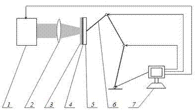
[0016] A combined process device for laser shock treatment of engine blades of the present invention is composed of a laser generator 1 , a focusing lens 2 , deionized water 3 , aluminum foil 4 , engine blades 5 , a six-degree-of-freedom manipulator 6 and a control system 7 .

[0017] The aluminum foil 4 in the combined process device for laser shock treatment of engine blades is pasted on the surface of the engine blade 5 to be treated; the deionized water 3 is covered on the aluminum foil 4; the engine blade 5 is clamped on the six-degree-of-freedom manipulator 6; The control system 7 is connected with the six-degree-of-freedom manipulator 6 and the laser generator 1 respectively.

[0018] The mater...


PUM


Abstract

The invention provides a combination method and apparatus for laser shock processing of an engine blade. The invention is characterized in that a blade shock strengthening area is divided into a marginal region, a transition region I and a transition region II which are increasingly far away from the edge of the blade successively, power density of laser used in the marginal region, the transition region I and the transition region II gradually decreases while light spots in the regions gradually increase, so residual compressive stress smoothly transits from a blade marginal surface layer to an unprocessed area, thereby improving the fatigue life of the blade.

Description

technical field [0001] The invention relates to the technical field of laser shock strengthening, in particular to a combined method and device for laser shock treatment of engine blades. Background technique [0002] Laser shock peening is a new type of surface strengthening technology for materials. It can obtain a high-amplitude residual compressive stress layer on the surface of metal parts, which greatly improves the fatigue life of the parts. Compared with conventional shot peening technology, its residual compressive stress layer is deeper. At the beginning of the 21st century, the United States applied laser shock technology to the strengthening and remanufacturing of F101, F119 and F414 engine blades. [0003] Fatigue fractures of aircraft engine blades generally occur at the edge of the blade. Therefore, laser shock treatment is mainly performed on the edge of the blade, such as figure 1 As shown, the gray area is the laser shock treatment area. Generally, the las...

Claims


Application Information

Patent Timeline
Patent Type & Authority Applications(China)
IPC IPC(8): C21D7/04C21D1/09C21D9/00
Inventor 巩水利张永康戴峰泽邹世坤鲁金忠
Owner BEIJING AERONAUTICAL MFG TECH RES INST
Why Eureka
Try Eureka