Anti-impact stop valve sealing structure

A technology of sealing structure and globe valve, which is applied in the direction of lifting valve, valve details, valve device, etc., can solve the problems of short service life, deformation of sealing surface, etc., and achieve the effect of ensuring sealing performance and prolonging service life

Inactive Publication Date: 2013-07-17
SHANGHAI KAIWEIXI GRP CO LTD
View PDF10 Cites 4 Cited by
  • Summary
  • Abstract
  • Description
  • Claims
  • Application Information

AI Technical Summary

Problems solved by technology

[0002] With the continuous development of petrochemical and coal chemical equipment to high parameters, large scale and integration, a large number of quick cut-off pneumatic or hydraulic devices are required Globe valve, the switching time of the shut-off valve is very fast; Figure 1 is the sealing structure of the traditional globe valve. When the switching speed is relatively slow, the sealing surface will not be deformed or damaged due to the impact of axial force, resulting in the sealing failure of the globe valve; however, the traditional globe valve When the sealing structure is used in the case of fast switching, the sealing surface of the valve is easily impacted by the axial force quickly, causing the sealing surface to be deformed or damaged, resulting in the sealing failure of the globe valve and short service life.

Method used


Image

  • Anti-impact stop valve sealing structure
  • Anti-impact stop valve sealing structure

Examples


Embodiment Construction

[0019] Please refer to the accompanying drawings for a further description of the present invention.

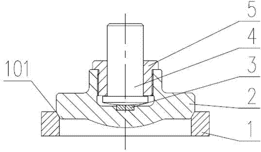
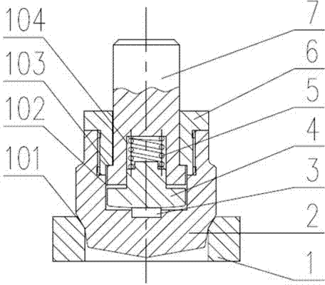
[0020] Such as figure 2 As shown, the present invention provides a sealing structure of an anti-shock stop valve, including a valve seat 1, a valve disc 2, a wear-resistant gasket 3, a buffer cover 4, a lock nut 5, a spring 6, a valve stem 7, and a valve disc 2 Installed on the valve seat 1, the contact surface of the valve disc 2 and the valve seat 1 forms a sealing surface 101, a concave hole 102 is arranged in the valve disc 2, and a wear-resistant gasket 3 is installed at the bottom of the concave hole 102, and the wear-resistant gasket 3 A buffer cover 4 is installed on the top, and a spring 6 is placed on the top of the buffer cover 4. A spring 6 is in close contact with the inner hole 104 indented at the bottom of the valve stem 7. The end of the valve stem 7 is provided with a boss 103, and the lock nut 5 is in contact with the valve. After the petal 2 is connected ...


PUM


Abstract

The invention discloses an anti-impact stop valve sealing structure. A valve clack is arranged on a valve base, the contact surface of the valve clack and the valve base forms a sealing surface, a recessed hole is arranged in the valve clack, a wear-resisting gasket is mounted at the bottom of the recessed hole, a buffer cover is arranged on the wear-resisting gasket, one spring is sleeved at the top of the buffer cover, one spring is tightly contacted with an inner hole retracted at the bottom of a valve rod, the end portion of the valve rod is provided with a boss, and a locking nut is connected with the valve clack to be locked tightly and then to press on the boss on the end portion of the valve rod. The anti-impact stop valve sealing structure has the advantages that the problem that the sealing surface of the valve is deformed or damaged caused by impact from rapid axial force can be effectively solved, service life of a stop valve sealing pair is prolonged, and sealability is good.

Description

Technical field [0001] The present invention involves the field of valve technology, which specializes in a sealing structure of anti -impact cuttering valve. It mainly uses industries such as petrochemical and coal chemical industry. The operating conditions require high -frequency and fast switching truncorated valves. Background technique [0002] With the continuous development of petrochemical and coal chemical devices to high -parameters, large -scale, and integrated development, the device needs to use a large amount of rapid cutting off -air or hydraulic cut -off valve to quickly cut off the switching time of the cut -off valve. figure 1 It is the sealing structure of the traditional cut -off valve. Under the slow switching speed, the covered cover will not cause the seal deformation or damage caused by the axial impact, causing the sealing of the cut -off valve.In the case of rapid switching, the valve cover surface is easily impacted by axial force, causing the sealing ...

Claims


Application Information

Patent Timeline
Patent Type & Authority Applications(China)
IPC IPC(8): F16K1/00F16K1/48F16K25/04
Inventor 吴建伟卓育成何伟华梁连金
Owner SHANGHAI KAIWEIXI GRP CO LTD
Why Eureka
Try Eureka