Tracking boost device used for power factor correction circuit and method
A technology of power factor correction and boosting device, which is applied in the output power conversion device, the conversion of DC power input to DC power output, electrical components, etc. The effect of efficiency
- Summary
- Abstract
- Description
- Claims
- Application Information
AI Technical Summary
Problems solved by technology
Method used
Image
Examples
Embodiment Construction
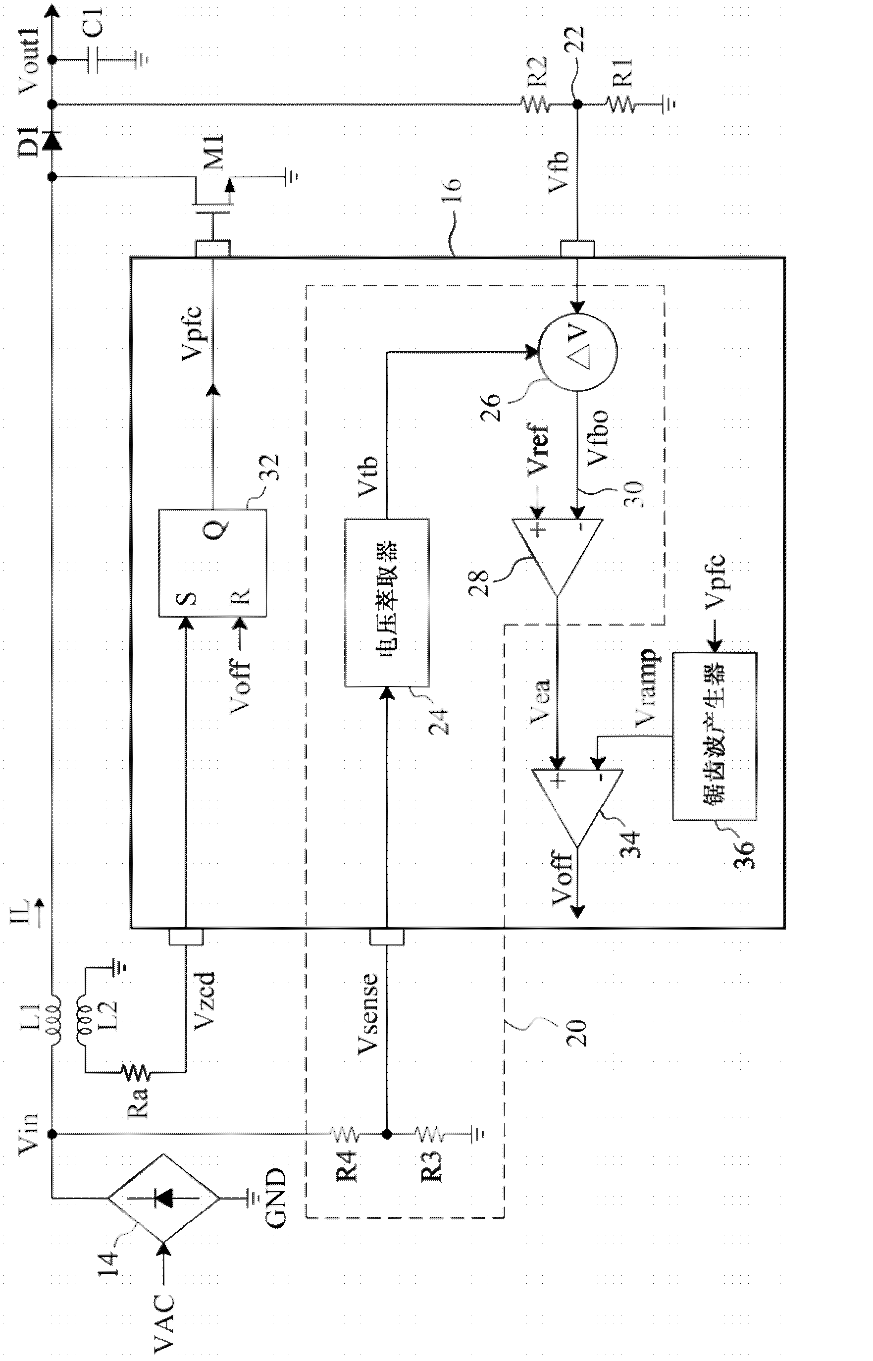
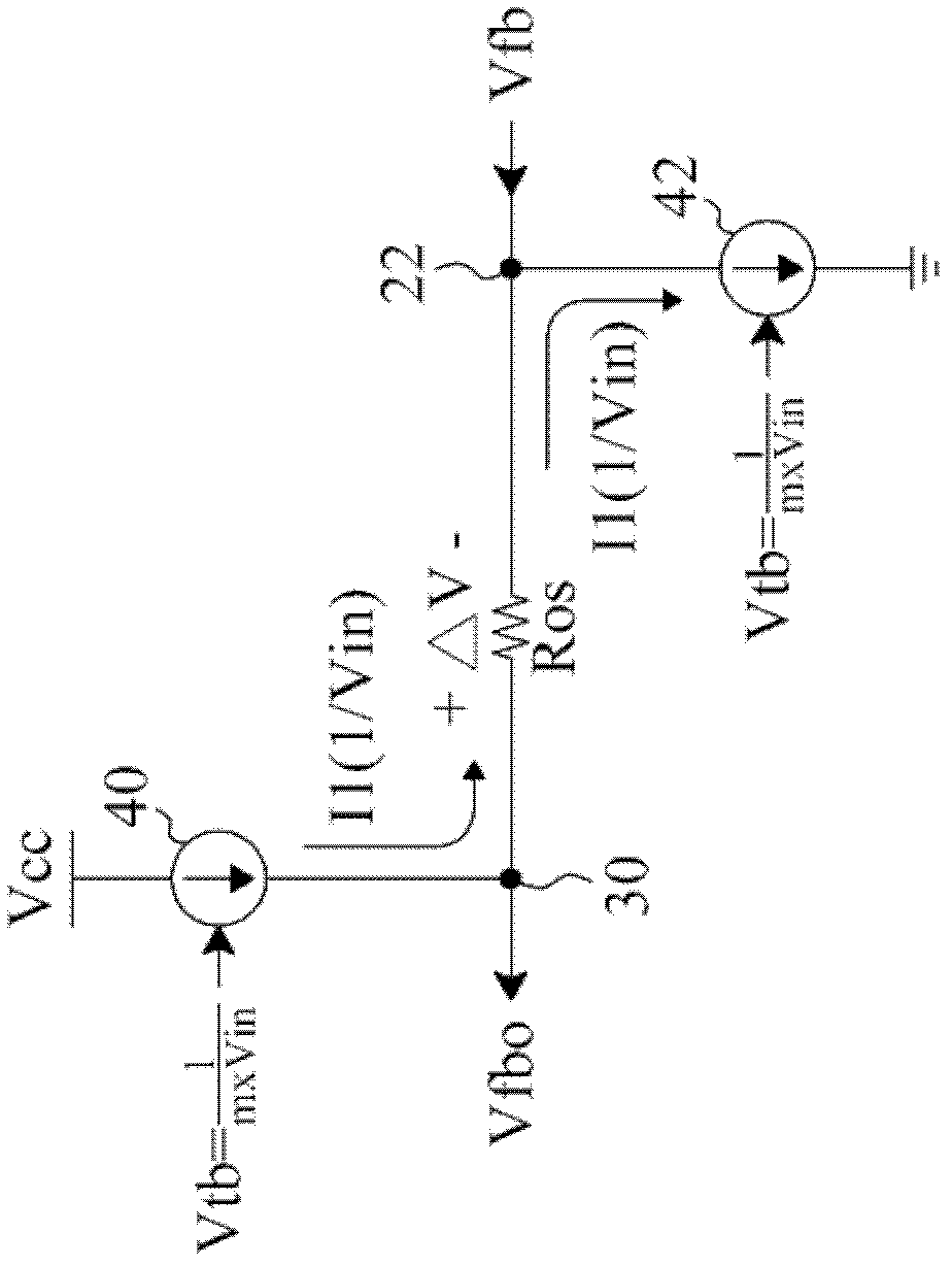
[0057] refer to figure 2 , the power factor correction circuit includes the tracking boost device 20 according to the present invention to provide an error signal Vea related to its input voltage Vin, the sawtooth wave generator 36 generates the sawtooth wave signal Vramp according to the drive signal Vpfc of the switch M1, and the comparator 34 compares the error signal Vea and the sawtooth wave signal Vramp generate an off signal Voff, the auxiliary coil L2 induces the current IL of the inductor L1 to generate a sensing signal Vzcd, and the trigger 32 generates a driving signal Vpfc according to the sensing signal Vzcd and the off signal Voff to switch the switch M1 to input the input voltage Vin Converted to the output voltage Vout1, and the resistors R1 and R2 form a voltage divider to divide the output voltage Vout1 to generate a feedback voltage Vfb at the output feedback terminal 22 for the tracking boost device 20 . Since the error signal Vea is related to the input v...
PUM
 Abstract
Description
Claims
Application Information
 - R&D
- Intellectual Property
- Life Sciences
- Materials
- Tech Scout
- Unparalleled Data Quality
- Higher Quality Content
- 60% Fewer Hallucinations
Browse by: Latest US Patents, China's latest patents, Technical Efficacy Thesaurus, Application Domain, Technology Topic, Popular Technical Reports.
© 2025 PatSnap. All rights reserved.Legal|Privacy policy|Modern Slavery Act Transparency Statement|Sitemap|About US| Contact US: help@patsnap.com


