A kind of eddy current composite spinning method for producing fancy yarn

The technology of a vortex spinning gauze and composite spinning gauze, which is used in the field of textile processing, can solve problems such as poor combination, insufficient fiber grip, and decreased yarn molding quality

Inactive Publication Date: 2016-01-06
WUHAN TEXTILE UNIV +1
View PDF10 Cites 18 Cited by
  • Summary
  • Abstract
  • Description
  • Claims
  • Application Information

AI Technical Summary

Problems solved by technology

[0003] There are limitations and bottlenecks in the existing vortex spinning technology: firstly, the thread fiber strands are introduced into the vortex chamber without adding twist, and the fiber strands entering the vortex chamber are drawn by the air flow during the vortex yarn forming process, and some The fibers can overcome the frictional cohesion of the surrounding fibers and separate from the yarn body, and are discharged with the airflow entering the discharge channel to form tow fibers, resulting in a decrease in yarn forming quality and waste of raw materials; The tail is twisted and twisted at high speed in a ring, which belongs to free-end non-holding spinning, which leads to insufficient holding force on fibers during spinning, low degree of internal and external transfer of fibers, poor degree of fiber cohesion, and low spinning strength. Fibers with poor cohesion and high stiffness cannot be spun into yarn
During the above-mentioned eddy current composite spinning, the core yarn is fed from the direction directly facing the yarn guide, and there is no obvious feeding angle with the yarn guide direction, so the fed core yarn is generally located in the core layer of the composite yarn, which cannot To achieve multi-color and multi-form wrapping of the filament yarn on the surface of the composite yarn, resulting in a multi-color effect

Method used


Image

  • A kind of eddy current composite spinning method for producing fancy yarn

Examples


Embodiment Construction

[0012] The present invention will be described in further detail below in conjunction with accompanying drawing

[0013] see Attachment

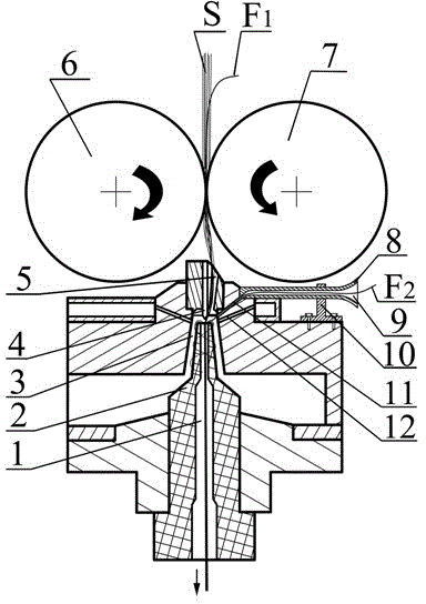
[0014]A vortex composite spinning method for producing fancy yarns, in which a yarn conveying channel 11 is arranged on the outer tube of each vortex spinning device of a vortex spinning machine, and the yarn conveying channel 11 is located in the gas conveying pipeline 12 and the fiber conveying channel 5 In between, the yarn delivery channel 11 is on the same side as the front rubber roller 7, so that the decorative yarn F2 can be guided and fed smoothly. The angle between the central axis of the yarn delivery channel 11 and the central axis of the guide pin 4 is 15-65°. The yarn outlet is located between the fiber outlet of the fiber delivery channel 5 and the yarn inlet of the yarn channel 1. The purpose is that after the decorative yarn F2 is fed into the vortex chamber 3, it can smoothly enter the yarn channel 1 under the action of air...


PUM


Abstract

The invention relates to a vortex composite spinning method for producing structured yarns, which belongs to the technical field of textile processing. According to the method, a yarn conveying channel which forms an included angle of 15-65 degrees with a guide pin is formed on each vortex spinning device outer tube of a vortex spinning machine; the yarn conveying channel is positioned on the same side as a front rubber roll; a yarn outlet of the yarn conveying channel is positioned at the fiber outlet of a fiber conveying channel and the yarn inlet of a yarn channel; the yarn inlet of the yarn conveying channel is communicated with a yarn leading channel of a yarn leading tube; and decorative yarns F2 are directly fed into the yarn inlet of the yarn channel without passing through a front jaw, and are wound on the surfaces of vortex core-spun yarns formed by F1 and short fiber rods S, so that the vortex composite structured yarns are formed. Due to the adoption of the method, short fibers produced in the conventional vortex spinning process can be prevented from being taken away by air flow, the fiber falling rate of short fibers is lowered, the yarn forming capacity during vortex composite spinning is improved greatly, end breakage of resultant yarns is eliminated, the requirements of vortex resultant yarns on a short fiber raw material are lowered, and the spinnable fiber raw material range of the vortex spinning is expanded greatly.

Description

technical field [0001] The invention relates to a vortex composite spinning method for producing fancy yarns, which belongs to the technical field of textile processing. technical background [0002] Vortex spinning technology is a free-end spinning method that uses high-speed rotating vortex airflow to twist the fiber flow into yarn. The spinning process is as follows: the fiber strands are transported to the inside of the vortex chamber along the fiber feeding channel. Due to the existence of the twist-resistance component in the exit area of ​​the fiber feeding channel, the fiber strands are kept in the state without adding twist and are introduced into the vortex chamber. The front end of the fiber directly enters the yarn guiding channel of the spindle-shaped yarn guide shaft body, while the tail end of the fiber remains in the fiber feeding channel while being held by the jaws of the front roller. When the tail end of the fiber is no longer held by the front roller ja...

Claims


Application Information

Patent Timeline
Patent Type & Authority Patents(China)
IPC IPC(8): D01H4/02D01H4/38
Inventor 夏治刚凌良仲徐卫林刘云周卫东叶汶祥陈军
Owner WUHAN TEXTILE UNIV
Why Eureka
Try Eureka