
Method for extracting natural gas hydrate through CO2/N2 underground replacement

A technology for hydrate and natural gas, which is applied in the direction of production fluid, earthwork drilling, wellbore/well components, etc., and can solve problems such as low permeability and low heat and mass transfer in hydrate layers

Inactive Publication Date: 2013-07-24
JILIN UNIV
View PDF7 Cites 43 Cited by
  • Summary
  • Abstract
  • Description
  • Claims
  • Application Information

AI Technical Summary

Problems solved by technology

This method has the advantages of economy, environmental protection and safety. It also sequesters carbon dioxide while exploiting natural gas, and also solves the problem of production efficiency due to the low heat and mass transfer and low permeability of the hydrate layer.

Method used


Image

  • Method for extracting natural gas hydrate through CO2/N2 underground replacement

Examples


Embodiment 1

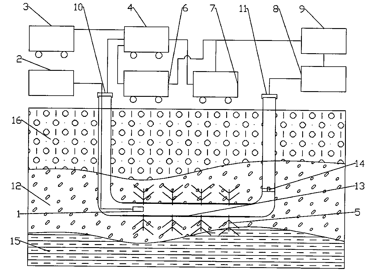
[0022] Example 1: Reduced pressure mining combined with CO 2 / N 2 Displacement mining, see figure 1 Shown:

[0023] Step 1: Implement two vertical wells—injection well 10 and production well 11. The two vertical wells pass through the hydrate overlying formation 16 to the hydrate layer 12. The horizontal well 13 is set in the hydrate layer 12. The horizontal well 13 The length and number of layers are determined according to the scope and thickness of hydrate reservoirs; after the drilling is completed, cementing and completion are carried out, and some monitoring instruments such as temperature sensors, pressure sensors and flow meters are installed to monitor the downhole temperature, pressure and flow rate. and other parameters are monitored, and the monitoring instrument 1 is connected to the surface data acquisition and processing system 2 to collect and process the data for analysis of the mining process and next-step work guidance. A hydrate layer 12 is located on an...

Embodiment 2

[0028] Example 2: Liquid CO 2 Displacement bound CO 2 / N 2 Displacement mining, see figure 1 Shown:

[0029] Step 1: Same as Step 1 in Example 1.

[0030] Step 2: The process is roughly the same as Step 2 in Example 1, except that liquid CO is used 2 As a fracturing fluid, CO 2 Preparation of CO in cart 6 2 Carry out liquefaction, pump into the closed mud sand device vehicle 3, and then pump into the well through the fracturing pump vehicle 4 to implement the fracturing process.

[0031] Step 3: After the fracturing is completed, adjust the pressure to the pressure range of the replacement reaction, and carry out CO2 replacement production; after a period of replacement, control the gas production pressure through the pressure controller on the plug 14, and the gas collected from the production well 11 passes through the gas The liquid separation device 8 performs gas-water separation, and then performs gas separation through the gas separation device 9 to store natural...


PUM


Abstract

The invention discloses a method for extracting natural gas hydrate through CO2 / N2 underground replacement. The method includes that CO2 / N2 is injected into a hydrate layer, temperature and pressure in a well are controlled, replacement reaction is carried out to obtain methane and CO2 / N2 hydrate, extracting of the natural gas hydrate is achieved, through the horizontal abutting joint well technology and the fracturing technology, the contact area of the reaction is enlarged, and extracting efficiency is improved; first, well drilling, well cementation and well completion of a horizontal abutting joint well are carried out, according to the layer thickness and the range of the hydrate, the length and the layer number of a horizontal well section are confirmed; then the fracturing technology is carried out on a layer to be extracted in the mode of staged fracturing; and fracturing fluid is removed, depressurizing extracting is carried out, after a period of time, extracting speed is reduced obviously, CO2 / N2 is injected in, the pressure in the well is controlled, and replacement extracting is carried out. Efficient replacement extracting of the natural gas hydrate is achieved, environment benefits and economical benefits are remarkable, and the method can be used for large-scale extracting of the natural gas hydrate in a freeze soil area and the natural gas hydrate.

Description

technical field [0001] The invention relates to a natural gas hydrate mining method, in particular to a CO 2 / N 2 The invention relates to a method for underground replacement and exploitation of natural gas hydrate, which belongs to the technical field of energy. Background technique [0002] Natural gas hydrate refers to a cage-shaped crystal substance formed by natural gas and water at a specific temperature and pressure (low temperature and high pressure). It looks like ice and snow. Because it can be ignited, it is commonly called "combustible ice". At the beginning of the research, the main purpose was to suppress the formation of natural gas hydrates in gas pipelines. However, with the continuous development of the economy, the demand for energy is increasing, and the energy shortage is becoming more and more serious. Therefore, natural gas hydrates have gradually attracted the attention of scientists at home and abroad. Related exploration, mining and experimental ...

Claims


Application Information

Patent Timeline
IPC IPC(8): E21B43/16E21B43/01E21B43/267E21B43/34
CPCE21B41/0099
Inventor 孙友宏李冰郭威贾瑞刘卫卫
Owner JILIN UNIV
Learn More