Air-cooling condenser structure containing horizontal shaft axial flow fan group

A technology for air-cooled condensers and axial flow fans, which is applied to steam/steam condensers, lighting and heating equipment, etc., and can solve the problem of limited flow at the inlet of axial flow fans, distortion of flow at the inlet of axial flow fans, and difficult driving of fans Cooling air flow and other issues, to avoid serious distortion of fan inlet flow, reduce pipeline consumption and project cost, and improve aerodynamic performance

Inactive Publication Date: 2013-07-24
NORTH CHINA ELECTRIC POWER UNIV (BAODING)
View PDF4 Cites 11 Cited by
  • Summary
  • Abstract
  • Description
  • Claims
  • Application Information

AI Technical Summary

Problems solved by technology

In addition, under the action of ambient wind, the cross-flowing airflow will aggravate the flow deformation at the inlet of the axial flow fan, resulting in a sharp decrease in the performance of the fan, especially for the air-cooled unit upstream of the wind farm. Not only is it difficult for the fan to drive the cooling air flow, but even downstream Extremely unfavorable situation where hot air from the outlet of the air cooling unit flows back into the upstream unit
[0003] To sum up, it is necessary to address the shortcomings of the existing air-cooled condenser unit layout, such as serious flo

Method used


Image

  • Air-cooling condenser structure containing horizontal shaft axial flow fan group
  • Air-cooling condenser structure containing horizontal shaft axial flow fan group

Examples


Embodiment Construction

[0010] The present invention proposes a novel structure of an air-cooled condenser including a group of horizontal-axis and axial-flow fans. The present invention will be described below in conjunction with the accompanying drawings.

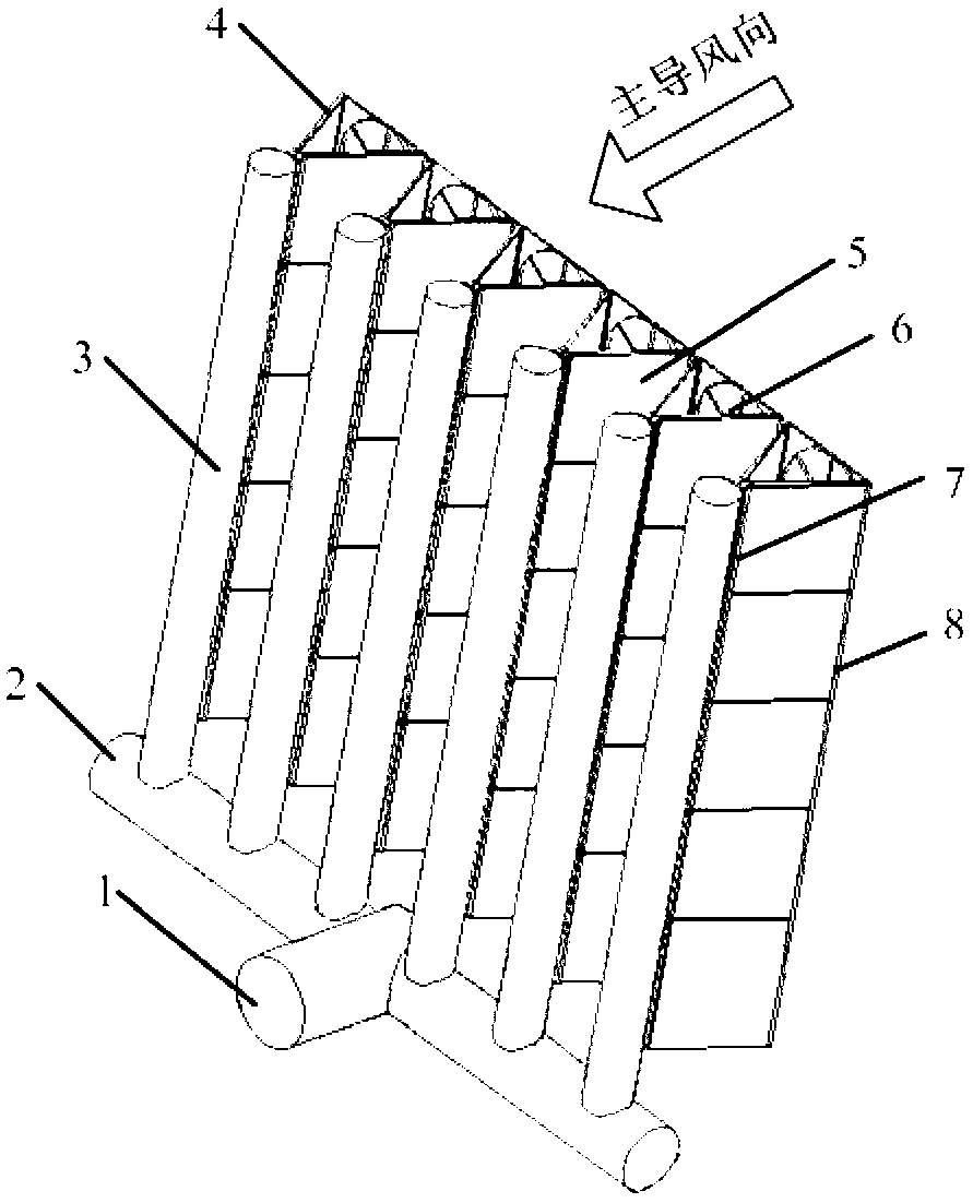
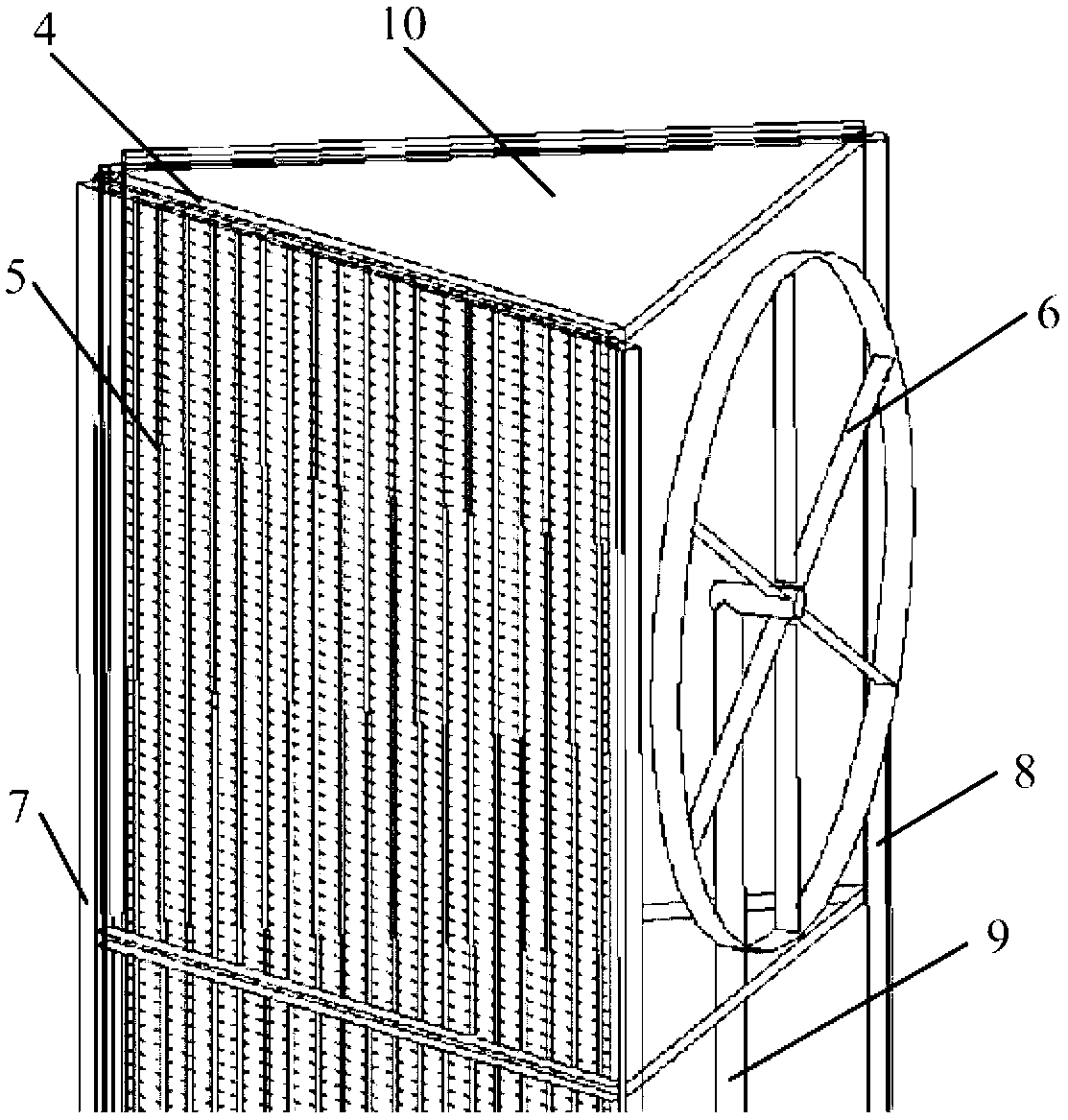
[0011] exist figure 1 In the schematic diagram of the structure of the air-cooled condenser including the horizontal axial flow fan group, the main steam pipe 1 and the horizontal steam branch pipe 2 are welded in a cross, and each row of vertical steam distribution pipes 3 is welded vertically on the horizontal steam branch pipe 2 at equal distances. , along the axial direction of the steam distribution pipe 3, the fixed support column 7 and the triangular bottom column 8 form a triangular frame structure with the upper and lower surfaces 10 of the welded tube bundle parallel to the axial direction of the steam distribution pipe. The finned tube bundles 5 are arranged vertically (such as figure 2 shown) and connected to the steam distribution...


PUM


Abstract

The invention discloses an air-cooling condenser structure containing a horizontal shaft axial flow fan group and a vertically-arranged fin tube bundle and belongs to the technical field of power station air cooling. The air-cooling condenser structure is formed by a main exhaust pipeline, a horizontal steam branch pipe, a vertical steam distribution pipe, an air-cooling condenser fin tube bundle arranged vertically in a layered mode and horizontal shaft axial flow fans. Steam turbine exhaust steam passes through a main steam pipeline and a horizontal steam branch pipe, enters the vertical steam distribution pipe, and then enters the fin tube bundle through a steam distribution header. The fin tube bundle is divided into two columns and forms a triangular structure, the fin tube bundle columns are perpendicular to the ground and arranged in parallel in the layered mode along the height direction, and the planes of impellers of the fan group are arranged to face toward the predominant wind direction of a power station. According to the air-cooling condenser structure, the conditions of air flow deformation of fan inlets can be improved, kinetic energy of an environmental wind field is effectively used, thermal performance of a direct air cooling system is improved, further the number of exhaust pipelines to be used and floor area of the exhaust pipelines in the direct air cooling system can be reduced, and investments and cost of the system are reduced.

Description

technical field [0001] The invention belongs to the technical field of power station air cooling. In particular, it relates to an air-cooled condenser structure including a group of horizontal-axis axial-flow fans. Specifically, the energy of the ambient wind field is used to arrange the axial fan group of the air-cooled condenser in layers facing the dominant wind direction of the ambient wind. An air-cooled condenser layout structure that includes horizontal axial flow fan groups and vertically arranged finned tube bundles can reduce the amount of steam pipes and reduce the footprint of the air-cooled island. Background technique [0002] In the past ten years, direct air-cooled power plants have achieved rapid development in coal-rich and water-short areas in northern my country. The air-cooled condenser of the direct air-cooled unit includes dozens of air-cooled units in an A-frame structure, and each air-cooled unit is composed of finned tube bundle heat exchangers ar...

Claims


Application Information

Patent Timeline
IPC IPC(8): F28B1/06F28B9/00
Inventor 杨立军杜小泽杨勇平
Owner NORTH CHINA ELECTRIC POWER UNIV (BAODING)
Why Eureka
Try Eureka