
Sun position detection device and method

A detection device and technology of the sun position, which is applied in the direction of measuring device, measuring angle, surveying and navigation, etc., can solve the problems of sensor influence, large error of photoelectric four-quadrant sensor, sensor can not judge, etc., to expand the tracking range and tracking accuracy The effect of improving and improving tracking efficiency

Inactive Publication Date: 2013-07-24
DALIAN GREAT OCEAN NEW ENERGY DEV +1
View PDF7 Cites 11 Cited by
  • Summary
  • Abstract
  • Description
  • Claims
  • Application Information

AI Technical Summary

Problems solved by technology

[0004] The sun position detection device in the prior art has the following defects: (1) The photoelectric four-quadrant sensor uses a silicon battery as the core component. The silicon battery has high requirements on the light source, and the detection angle of the photoelectric four-quadrant sensor is very small, generally around 20° , when the detection angle is too large, there will be multiple light sources such as the light spot formed by the condenser lens and the sun spot in the field of view of the photoelectric four-quadrant sensor. The error of the quadrant sensor becomes larger or directly causes the failure of the photoelectric four-quadrant sensor. Therefore, the solar sensor of the existing design cannot detect the position of the sun in a wide range
(2) The photoelectric four-quadrant sensor is an analog sensor, which is more easily affected by stray light, and when the reflection of clouds in the sky is strong, it will have a great impact on the sensor and affect the stability of the tracking system

Method used


Image

  • Sun position detection device and method
  • Sun position detection device and method
  • Sun position detection device and method

Examples


Embodiment Construction

[0026] The present invention provides a sun position detection device and method, and the technical solution of the present invention will be described in detail below in conjunction with the accompanying drawings.

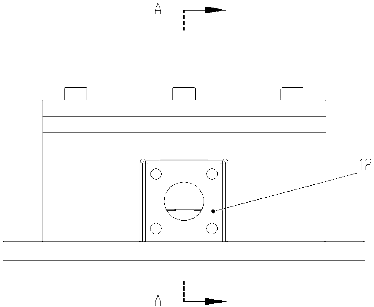
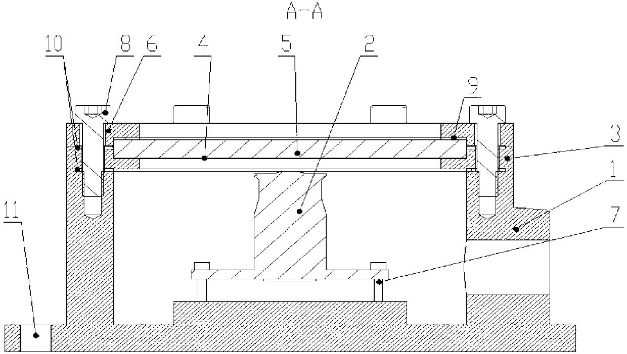
[0027] figure 2 It is a structural schematic diagram of an embodiment of the sun position detection device of the present invention, image 3 is the sun position detection device of the present invention figure 2 The cross-sectional view along the A direction, as shown in the figure, the sun position detection device includes a base, and also includes a casing 1, an upper cover 6, and the casing 1, upper cover 6 and the base form a cavity, and the camera that collects the sun image is connected by the camera mounting screw 7 2 is arranged on the base in the cavity, and the upper cover 6 includes a light-shielding part located around and a light-transmitting part located in the center. The casing 1 and the upper cover 6 can be fixed in any way. In this embodime...


PUM


Abstract

The invention discloses a sun position detection device and method. The device comprises a base, a shell and an upper cover; the shell, the upper cover and the base form a cavity; a camera for collecting solar image is arranged on the base in the cavity; and the upper cover comprises surrounding shading part and a transmitting part located in the center. The invention has the following advantages: (1) the digital camera avoids the high requirements of silicon cell on light source, so that the detection angle (field angle) changes with the light source to a desired size to expand the tracking range on the sun and improve the tracking efficiency; (2) a CCD sensor and a COMS sensor can identify the photos by domains to remove the interference image and obtain a real image of the sun, thereby greatly increasing the tracking precision; and (3) the control signal is output through a way that a single chip microcomputer collects photos and conducts operation analysis on the photo, and the digital collection process overcomes the problem of large error of simulation acquisition.

Description

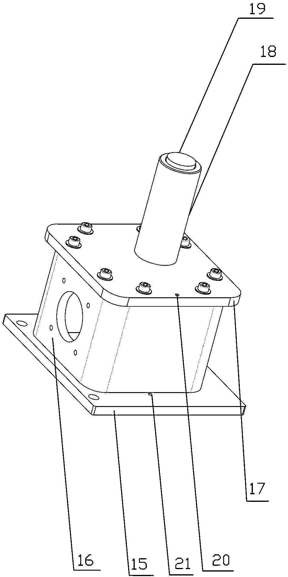
technical field [0001] The invention relates to a solar thermal power generation system, and more specifically, to a sun position detection device and method. Background technique [0002] The sun position detection device is used to track the sun position, and is used in a solar thermal power generation system. The structure of the sun position detection device in the prior art is as follows figure 1 shown. The device comprises a first base 15, a photoelectric four-quadrant sensor is arranged on the first base 15, a first housing 16 is arranged on the periphery of the photoelectric four-quadrant sensor, a first upper cover 17 is arranged on the first housing 16, and the first upper cover 17 is arranged on the first housing 16. Cover 17, the first base 15 sealing connection, on the first loam cake 17 vertically set light guide tube 18, the top of light guide tube 18 is provided with quartz mirror 19, the center of the photoelectric four-quadrant sensor of sensor, the center...

Claims


Application Information

Patent Timeline
IPC IPC(8): G01C1/00G05D3/12
Inventor 周改改王振声范鑫鸿王菲
Owner DALIAN GREAT OCEAN NEW ENERGY DEV
Learn More