Planar ultra wide band filtering antenna adopting short circuit lead

A technology of short-circuit lead and filter antenna, which is applied in the direction of slot antenna, antenna grounding device, antenna support/installation device, etc., can solve the problems of simultaneous realization and unfavorable selection, and achieve improved antenna gain, gain and direction stability, frequency The effect of bandwidth

Inactive Publication Date: 2013-07-24
SOUTH CHINA UNIV OF TECH
View PDF4 Cites 11 Cited by
  • Summary
  • Abstract
  • Description
  • Claims
  • Application Information

AI Technical Summary

Problems solved by technology

[0007] However, the above two existing technologies can only use a fixed antenna structure to realize one of the functions of trapping and improving the in-band characteristics of the antenna, which cannot be realized at the same time, and it is not conducive to people to choose according to actual needs.

Method used


Image

  • Planar ultra wide band filtering antenna adopting short circuit lead
  • Planar ultra wide band filtering antenna adopting short circuit lead
  • Planar ultra wide band filtering antenna adopting short circuit lead

Examples


Embodiment 1

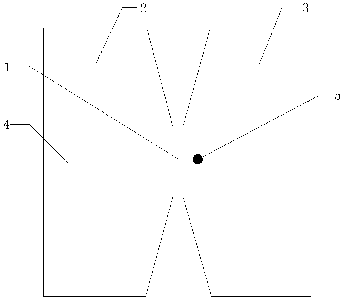
[0033] like image 3 As shown, the planar ultra-wideband filter antenna of this embodiment includes a double-sided PCB circuit board, and the double-sided PCB circuit board includes a PCB bottom layer structure and a PCB top layer structure, and the center of the PCB bottom layer structure is provided with a slit 1. The left and right sides of the gap are respectively provided with a floor 2 and a transmitter 3, and a pair of wedge-shaped structures are formed between the floor 2 and the transmitter 3; a feed circuit is provided on the top layer of the PCB, and the feed circuit is composed of a 50Ω The microstrip feeder 4 is composed of a via hole 5, the microstrip feeder 4 is connected to the transmitter 3 through the via hole 5, and the antenna structure is marked as an A-type structure.

[0034] In the A-type structure, a pair of wedge-shaped structures can generate two resonance modes, provide broadband matching, and improve return loss.

Embodiment 2

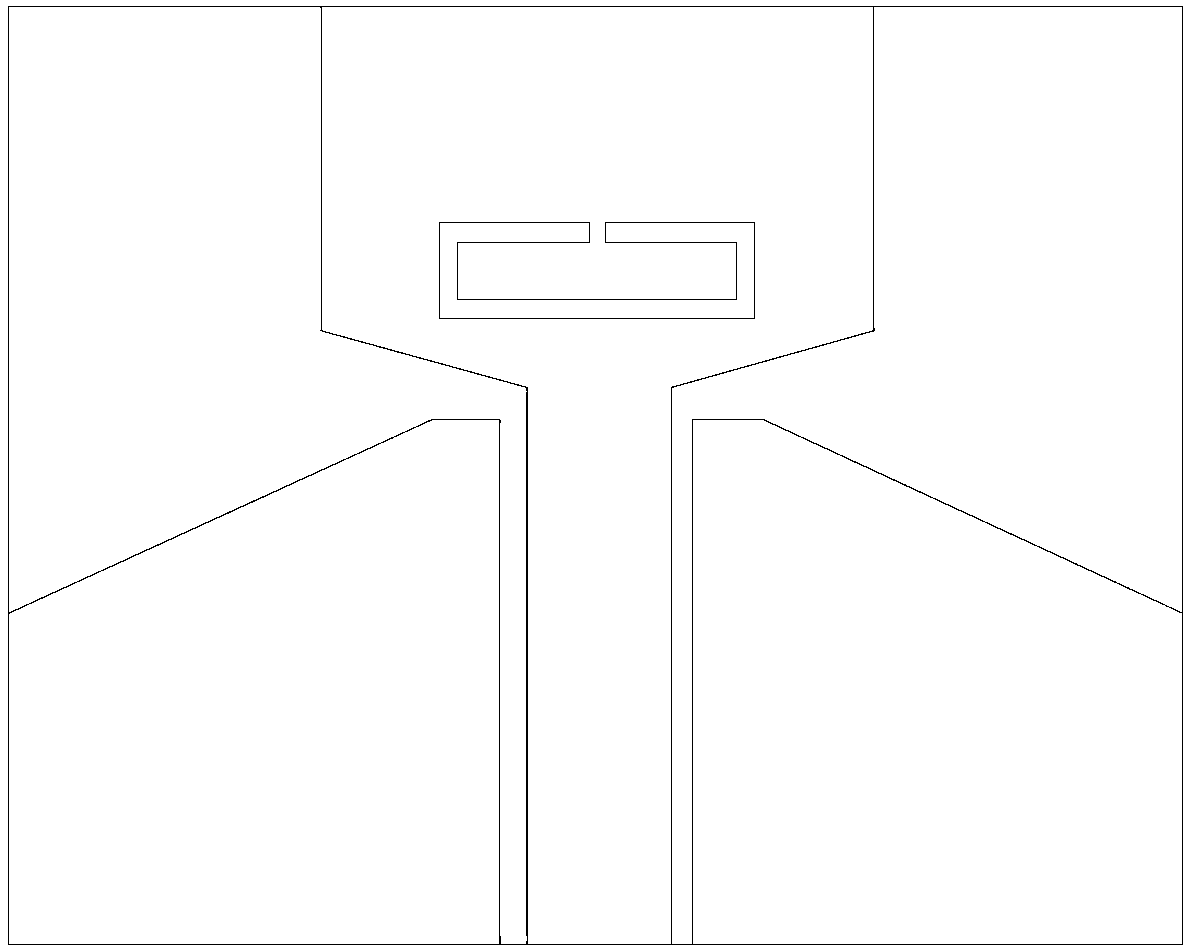
[0036] like Figure 4 As shown, the planar ultra-wideband filter antenna of the present embodiment, on the basis of the A-type structure, is provided with two short-circuit leads 6 of 1 / 2 wavelength, and the short-circuit leads 6 of the two 1 / 2 wavelengths are connected in parallel to the Between the floor 2 and the transmitter 3, the antenna structure is marked as a B-type structure.

[0037] In the B-type structure, since two short-circuit leads 6 of 1 / 2 wavelength connect the floor 2 and the transmitter 3, it is equivalent to providing two cross-slot loadings, and these two loadings have an effect on the out-of-band generation of the ultra-wideband antenna. Influence.

[0038] like Figures 5a-5b As shown, the current distribution of B-type structure 4.5GHz (ultra-wideband antenna low frequency band) and 9.5GHz (ultra-wideband antenna high-frequency band) respectively, the two high and low resonance frequencies together constitute the impedance matching network of the ent...

Embodiment 3

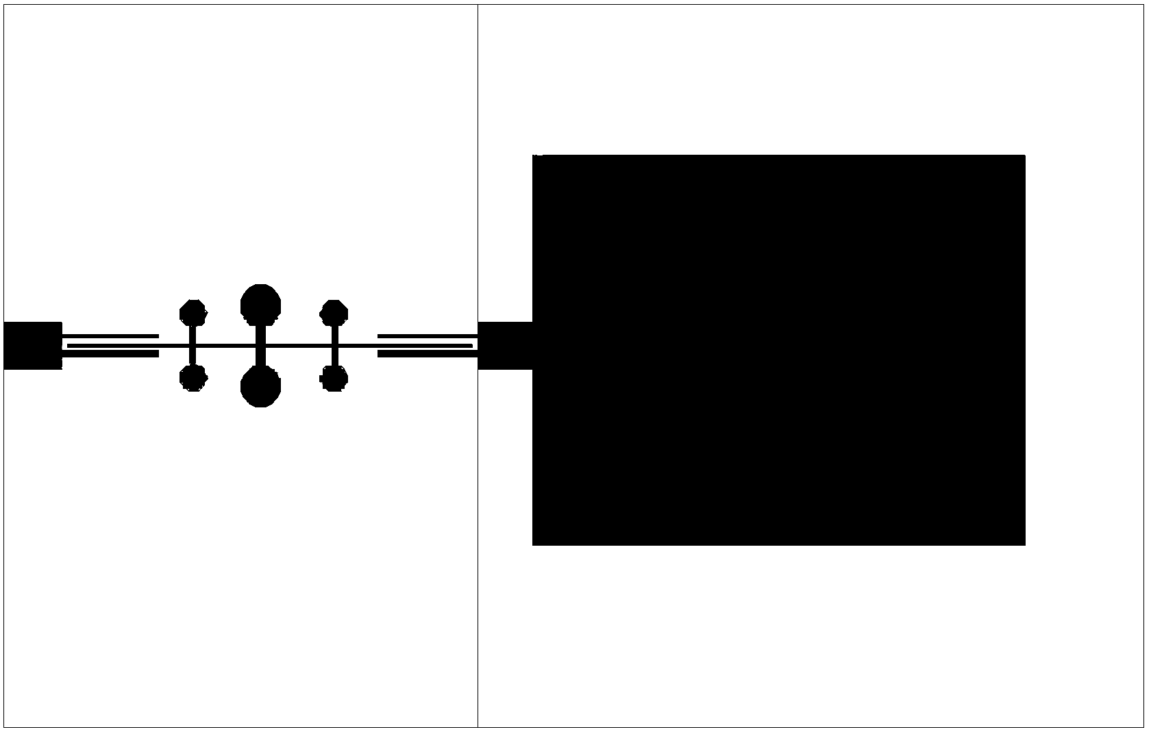
[0040] like Figure 6 As shown, the planar ultra-wideband filter antenna of the present embodiment, on the basis of the B-type structure, is provided with two short-circuit leads 7 of 1 / 4 wavelength, and the short-circuit leads 7 of the two 1 / 4 wavelengths are respectively connected with the microstrip feeder 4 in parallel, the antenna structure is recorded as a C-type structure.

[0041] like Figure 7 As shown, it can be seen that the C-type structure has better frequency selectivity at the high cut-off frequency than the B-type structure, because the short-circuit line of 1 / 4 wavelength is equivalent to a low-pass filter, so the C-type structure is Both the high and low cut-off frequencies have rolling characteristics, so that the entire ultra-wideband antenna has good frequency selectivity. In addition, it can also be seen that the A-type structure and the B-type structure have two emission zero points f 1 , f 2 , f 2 =2*f 1 , by controlling f 1 can control f 2 , w...


PUM


Abstract

The invention discloses a planar ultra wide band filtering antenna adopting a short circuit lead, comprising a double-sided PCB (printed circuit board), wherein the double-sided PCB comprises a PCB bottom layer structure and a PCB top layer structure, a gap is machined in the center of the PCB bottom layer structure, a floor and an emitter are respectively arranged at the left and right sides of the gap, and a pair of wedged structures used for generating a resonant mode to provide broadband matching is formed between the floor and the emitter; a feed circuit is arranged on the PCB top layer structure, the feed circuit consists of a 50-ohm micro-strip feeder line and a via hole, and the micro-strip feeder line is connected with the emitter through the via hole. The planar ultra wide band filtering antenna provided by the invention solves the problem that the frequency band of a traditional antenna is narrow, overcomes the disadvantages of large size and bad in-band and out-band features of certain ultra wide band antennas, and can meet the requirements on miniaturization and broadband.

Description

technical field [0001] The invention relates to an ultra-wideband monopole antenna, in particular to a planar ultra-wideband filter antenna using a short-circuit lead, belonging to the field of wireless communication. Background technique [0002] With the rapid development of wireless communication technology, all kinds of electronic equipment are developing towards miniaturization and broadband, and as a bridge and air interface of wireless communication technology, it is bound to develop in this direction. The traditional antenna is composed of a fixed element, which has poor shielding, low integration, large size, and narrow frequency band. These factors make the traditional antenna unable to meet the needs of future wireless communication. Therefore, research on small broadband antennas has become an important topic. [0003] With the proposal and development of ultra-wideband communication technology theory, as an important part of ultra-wideband communication technol...

Claims


Application Information

Patent Timeline
Patent Type & Authority Applications(China)
IPC IPC(8): H01Q13/10H01Q1/48H01Q1/38H01Q1/22
Inventor 王世伟陈瑞森汪凯郑丽昇褚庆昕
Owner SOUTH CHINA UNIV OF TECH
Why Eureka
Try Eureka