Planar ultra wide band filtering antenna adopting short circuit lead
A technology of short-circuit lead and filter antenna, which is applied in the direction of slot antenna, antenna grounding device, antenna support/installation device, etc., can solve the problems of simultaneous realization and unfavorable selection, and achieve improved antenna gain, gain and direction stability, frequency The effect of bandwidth
- Summary
- Abstract
- Description
- Claims
- Application Information
AI Technical Summary
Problems solved by technology
Method used
Image
Examples
Embodiment 1
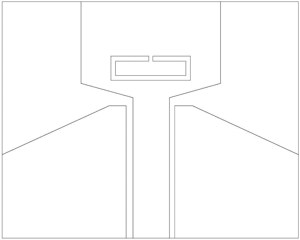
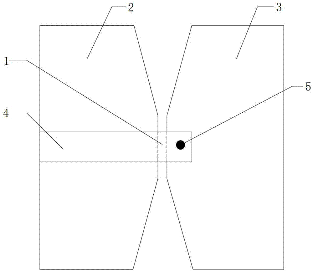
[0033] Such as image 3 As shown, the planar ultra-wideband filter antenna of this embodiment includes a double-sided PCB circuit board, and the double-sided PCB circuit board includes a PCB bottom layer structure and a PCB top layer structure, and the center of the PCB bottom layer structure is provided with a slit 1. The left and right sides of the gap are respectively provided with a floor 2 and a transmitter 3, and a pair of wedge-shaped structures are formed between the floor 2 and the transmitter 3; a feed circuit is provided on the top layer of the PCB, and the feed circuit is composed of a 50Ω The microstrip feeder 4 is composed of a via hole 5, the microstrip feeder 4 is connected to the transmitter 3 through the via hole 5, and the antenna structure is marked as an A-type structure.
[0034] In the A-type structure, a pair of wedge-shaped structures can generate two resonance modes, provide broadband matching, and improve return loss.
Embodiment 2
[0036] Such as Figure 4 As shown, the planar ultra-wideband filter antenna of the present embodiment, on the basis of the A-type structure, is provided with two short-circuit leads 6 of 1 / 2 wavelength, and the short-circuit leads 6 of the two 1 / 2 wavelengths are connected in parallel to the Between the floor 2 and the transmitter 3, the antenna structure is marked as a B-type structure.
[0037] In the B-type structure, since two short-circuit leads 6 of 1 / 2 wavelength connect the floor 2 and the transmitter 3, it is equivalent to providing two cross-slot loadings, and these two loadings have an effect on the out-of-band generation of the ultra-wideband antenna. influences.
[0038] Such as Figures 5a-5b As shown, the current distribution of B-type structure 4.5GHz (low frequency band of ultra-wideband antenna) and 9.5GHz (high frequency band of ultra-wideband antenna) respectively, the two high and low resonant frequencies together constitute the impedance matching networ...
Embodiment 3
[0040] Such as Image 6 As shown, the planar ultra-wideband filter antenna of the present embodiment, on the basis of the B-type structure, is provided with two short-circuit leads 7 of 1 / 4 wavelength, and the short-circuit leads 7 of the two 1 / 4 wavelengths are respectively connected with the microstrip feeder 4 in parallel, the antenna structure is recorded as a C-type structure.
[0041] Such as Figure 7 As shown, it can be seen that the C-type structure has better frequency selectivity at the high cut-off frequency than the B-type structure, because the short-circuit line of 1 / 4 wavelength is equivalent to a low-pass filter, so the C-type structure is There are roll-off characteristics near the high and low cut-off frequencies, so that the entire ultra-wideband antenna has good frequency selectivity. In addition, it can also be seen that the A-type structure and the B-type structure have two emission zero points f 1 , f 2 , f 2 =2*f 1 , by controlling f 1 can contr...
PUM
 Abstract
Description
Claims
Application Information
 - R&D
- Intellectual Property
- Life Sciences
- Materials
- Tech Scout
- Unparalleled Data Quality
- Higher Quality Content
- 60% Fewer Hallucinations
Browse by: Latest US Patents, China's latest patents, Technical Efficacy Thesaurus, Application Domain, Technology Topic, Popular Technical Reports.
© 2025 PatSnap. All rights reserved.Legal|Privacy policy|Modern Slavery Act Transparency Statement|Sitemap|About US| Contact US: help@patsnap.com


