Eureka AIR delivers breakthrough ideas for toughest innovation challenges, trusted by R&D personnel around the world.

Reservoir for a liquid medium having a suction device and a filter unit

A technology of suction device and liquid medium, which is applied to power devices, mufflers, exhaust devices, etc., can solve problems such as failure, SCR system failure, blockage, etc., and achieve the effect of prolonging service life

Inactive Publication Date: 2013-07-24
ROBERT BOSCH GMBH
View PDF7 Cites 2 Cited by
  • Summary
  • Abstract
  • Description
  • Claims
  • Application Information

AI Technical Summary

Problems solved by technology

Dirt particles stick to the filter or filter felt, which can lead to clogging
This in turn may cause the SCR system to malfunction or even fail

Method used


Image

  • Reservoir for a liquid medium having a suction device and a filter unit
  • Reservoir for a liquid medium having a suction device and a filter unit
  • Reservoir for a liquid medium having a suction device and a filter unit

Examples


Embodiment Construction

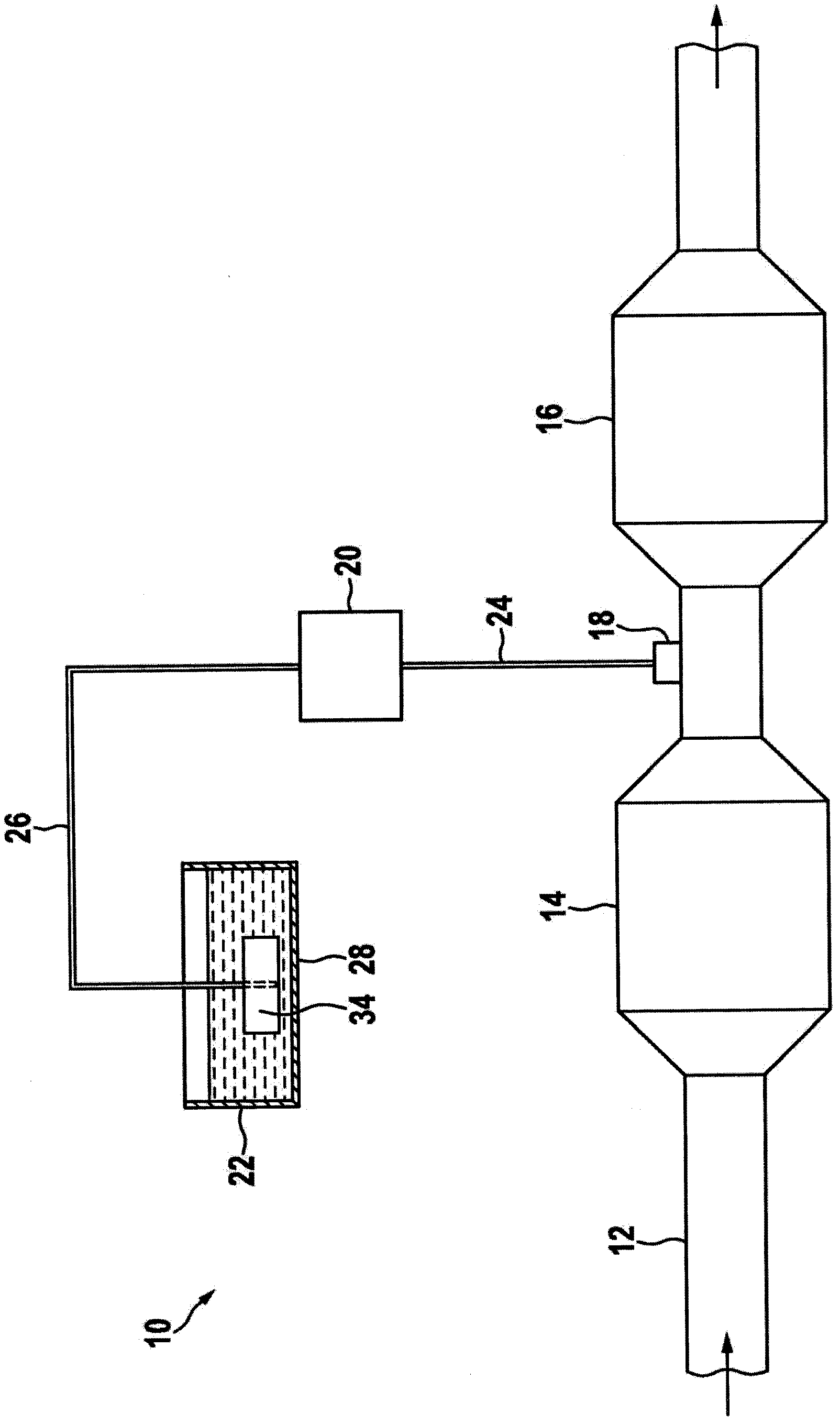
[0015] figure 1 An exhaust gas aftertreatment device 10 of an internal combustion engine is shown in a simplified and schematic manner as well as the environment in which the invention is represented. Exhaust gas aftertreatment device 10 includes an exhaust pipe 12 , an oxidation catalytic converter 14 and an SCR catalytic converter 16 . A particulate filter is not shown, which is usually arranged downstream of the oxidation catalyst 14 . The flow direction of the exhaust gas through the exhaust pipe 12 is marked by arrows (no reference numerals).

[0016] In order to supply the SCR catalyst 16 with a liquid reducing agent, for example an aqueous urea solution (so-called AdBlue) or another liquid reducing agent, a metering device 18 for the aqueous urea solution is arranged on the exhaust line 12 upstream of the SCR catalyst 16 . The metering device 18 injects an aqueous urea solution into the exhaust pipe 12 upstream of the SCR catalytic converter 16 as required.

[0017]...


PUM


Abstract

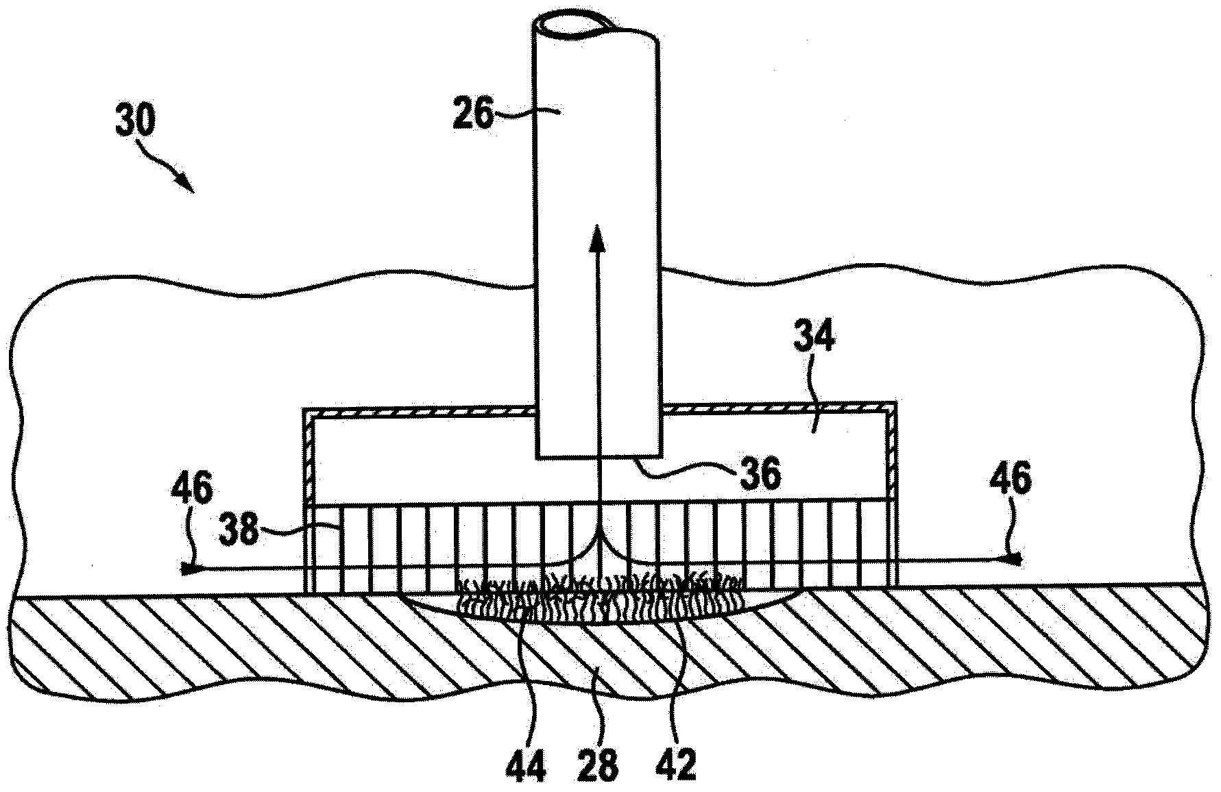
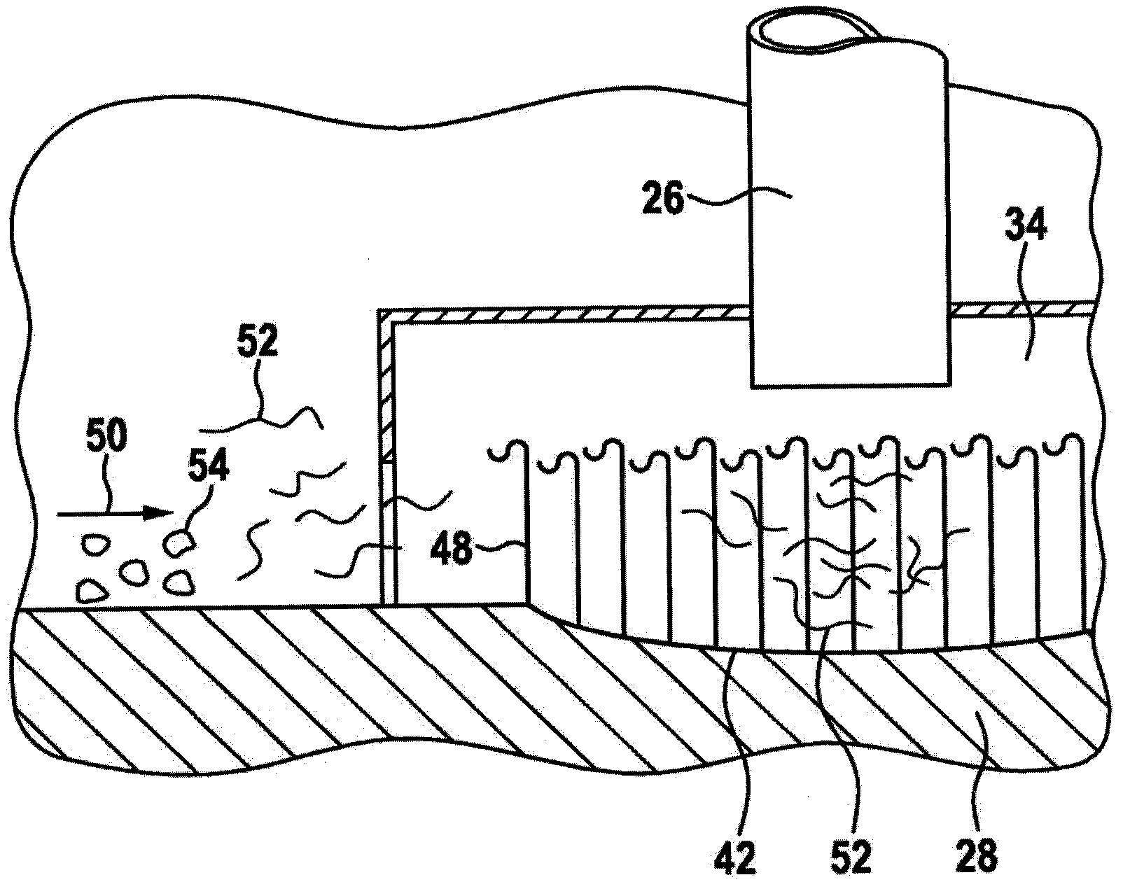
The invention relates to a reservoir (22) for a liquid medium, having a suction device (30) and a filter unit (34), wherein means for the sedimentation of particles and fibers are connected upstream of the filter unit (34).

Description

technical field [0001] The invention relates to an inhalation device with a filter unit arranged in a storage case. Background technique [0002] To operate a motor vehicle with an exhaust gas aftertreatment device with a catalytic converter for selective catalytic reduction (SCR), a liquid reducing agent - usually an aqueous urea solution (so-called AdBlue) - is injected from the storage tank In the exhaust pipe upstream of the SCR catalytic converter in flow direction. An example of such an exhaust gas aftertreatment device is known from DE 10 2006 012 855 A1. [0003] The AdBlue is conveyed from the storage tank into the suction hose via a conveying device, which includes, for example, a diaphragm pump. Suction devices are known to have a filter unit with or without filter felts in order to separate dirt particles from the liquid. Dirt particles get stuck in the filter or filter felt, which can lead to clogging. This in turn may cause the SCR system to malfunction or ...

Claims


Application Information

Patent Timeline
Patent Type & Authority Applications(China)
IPC IPC(8): F01N3/20
CPCF01N3/2066F01N2610/1426Y02T10/24F01N2610/1406B01D46/00F01N2610/02B60K2015/03236Y02A50/20Y02T10/12
Inventor J·德林J·汉内科W·埃姆斯曼
Owner ROBERT BOSCH GMBH
Why Eureka
Eureka Blog
Learn More