
Membrane stripping apparatus

A film stripping equipment and film stripping technology, applied in electronic equipment, lamination, application, etc., can solve the problems of limited application range, residual glue pollution, high cost, etc., and achieve the effect of reducing residual glue pollution and wide application range

Inactive Publication Date: 2013-07-31
BOE TECH GRP CO LTD +1
View PDF9 Cites 33 Cited by
  • Summary
  • Abstract
  • Description
  • Claims
  • Application Information

AI Technical Summary

Problems solved by technology

[0005] The technical problems to be solved by the present invention include, aiming at the problems that the existing stripping technology is easy to produce residual glue pollution, high cost and limited scope of application, to provide a stripping film that will not produce residual glue pollution, low cost and wide application range. Membrane equipment

Method used


Image

  • Membrane stripping apparatus
  • Membrane stripping apparatus
  • Membrane stripping apparatus

Examples


Embodiment 1

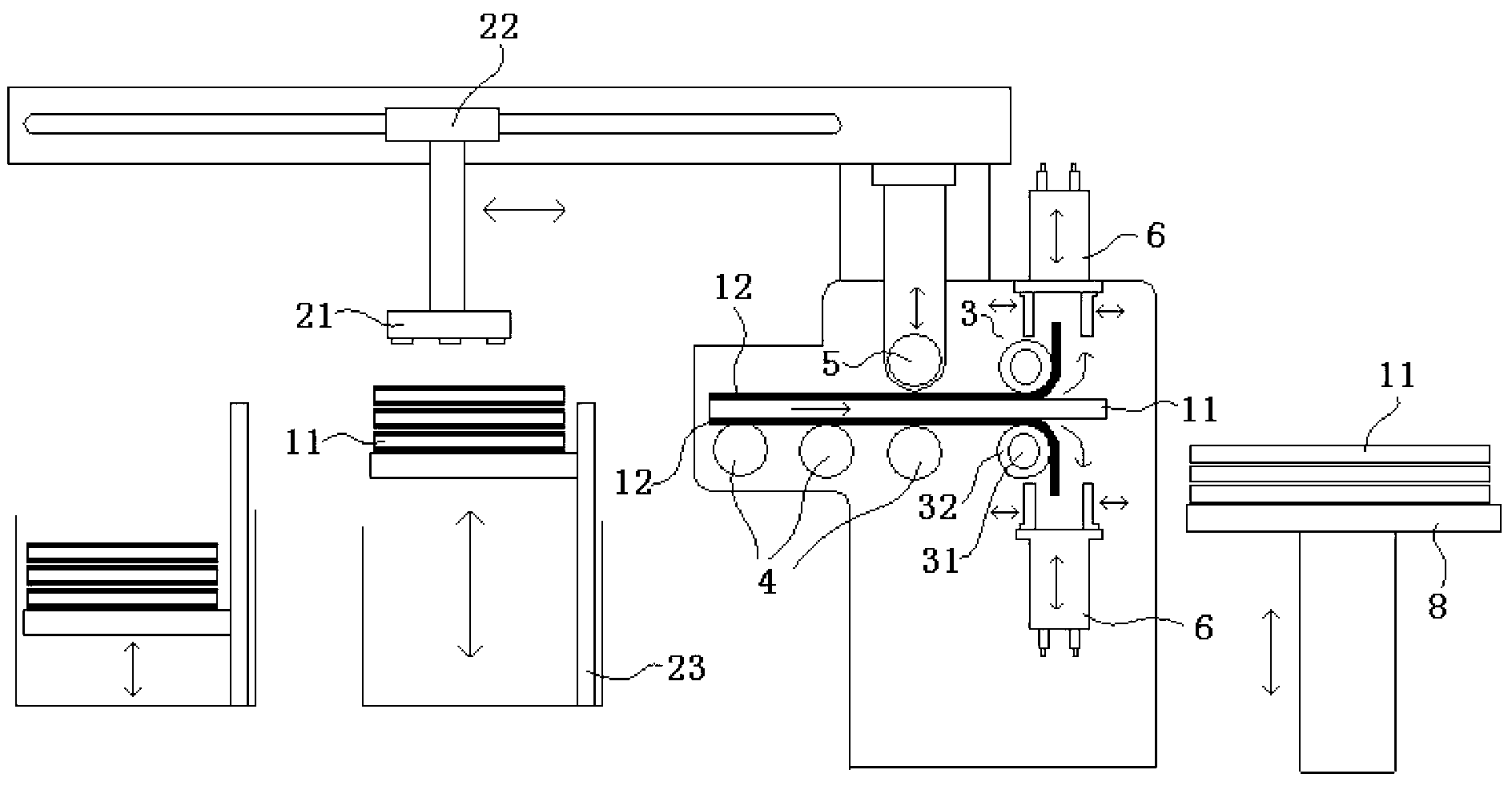
[0031] This embodiment provides a stripping device, such as figure 2 As shown, it includes two film peeling rollers 3, feeding mechanism, driving mechanism (not shown in the figure).

[0032] Wherein, the feeding mechanism is used to send the material 11 to be stripped between the two stripping rollers 3 (i.e. its feeding side, figure 2 middle left) for peeling.

[0033] Preferably, the feeding mechanism includes a feeding roller 4 or a feeding belt for supporting the material 11 to be peeled; the material 11 to be peeled can be moved by the rotation of the feeding roller 4 or the feeding belt.

[0034] This roller or belt feeding mechanism has the advantages of simple structure, low cost and reliable operation, and is suitable for both hard and soft materials 11 .

[0035] More preferably, the stripping device also includes a positioning mechanism located at the feeding side of the stripping roller 3, and the positioning mechanism includes a positioning roller 5 that is s...

Embodiment 2

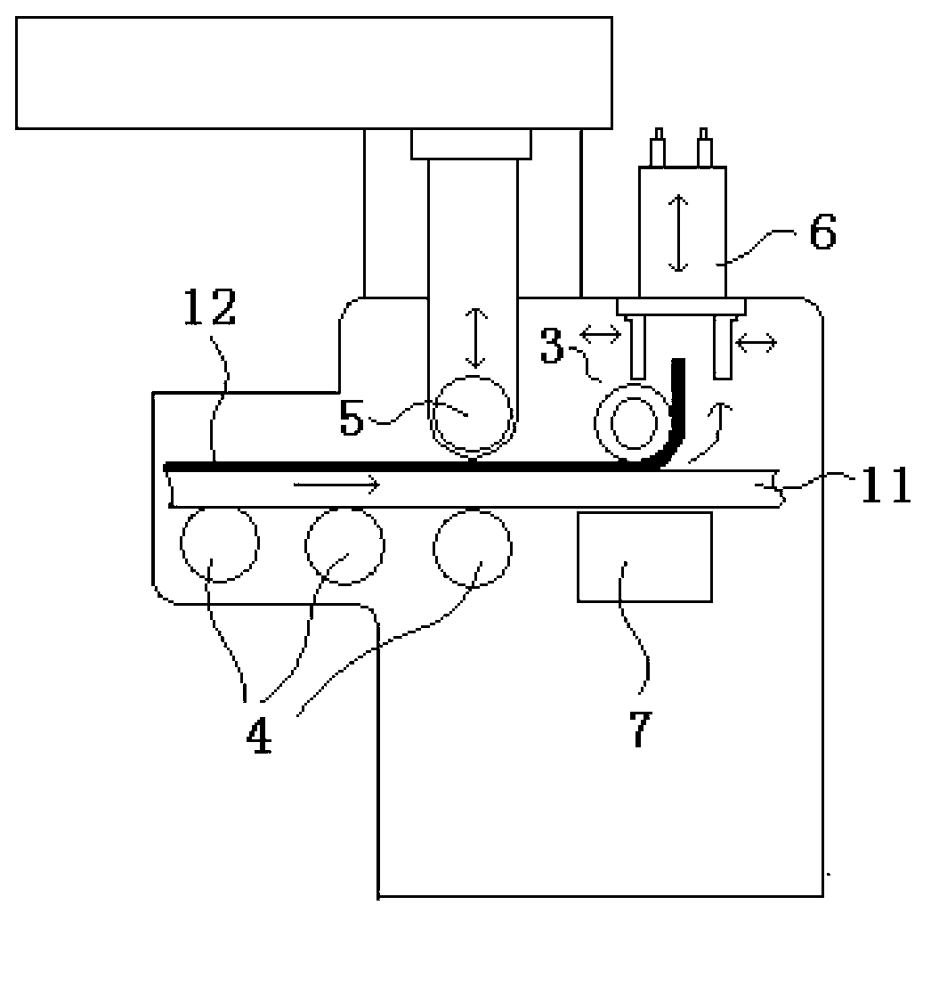
[0062] This embodiment provides a stripping device, which has a similar structure to the stripping device in Embodiment 1, the difference is that:

[0063] Such as image 3 As shown, in the film stripping equipment of this embodiment, opposite to the film stripping roller 3 is an adsorption mechanism 7 for absorbing the material 11 being stripped.

[0064] Obviously, some materials 11 have only one side of the film layer 12 that needs to be peeled off, so only one peeling roller 3 can be used to peel off the film, and because the peeling operation has only one active force on the material 11 in this case. One direction, so it is necessary to set the adsorption mechanism 7 opposite to the peeling roller 3 to prevent the material 11 from being deformed or taken away with the film layer 12 (especially for soft film materials).

[0065] Of course, there are various ways to realize that the peeling roller 3 and the adsorption mechanism 7 are relatively arranged; for example, it ca...


PUM


Abstract

The invention provides a membrane stripping apparatus, and belongs to the technical field of material membrane stripping. The membrane stripping apparatus can solve problems comprising easy generation of residual adhesive pollution, high cost and restricted application range of present membrane stripping technologies. The membrane stripping apparatus comprises at least one viscous membrane stripping roller, a feeding mechanism used for sending a material for membrane stripping to the feeding side of the membrane stripping roller, and a driving mechanism used for driving the membrane stripping apparatus to rotate. The membrane stripping apparatus is used for stripping one-sided or two-sided membranes comprising protection membranes and release membranes on the surfaces of materials having any component, size, thickness and shape, can be used for optical membranes, printing plates, display panels and the like, and is suitable for precise materials comprising ultrathin materials, high-precision printing plates and the like.

Description

technical field [0001] The invention belongs to the technical field of material stripping, and in particular relates to a stripping device. Background technique [0002] The surface of many product materials (such as film materials, plates, etc.) is attached with a protective film or release film for protection. For example, a large number of optical film materials (diffusion film, reflective film, polarizing film, etc.) are required to be used on the light guide plate and liquid crystal panel of the liquid crystal display device. Since these optical film materials are easily damaged, PE is attached to both surfaces. (polyethylene) or PET (polyethylene terephthalate) protective film, before use, it is obviously necessary to peel off these film layers. [0003] Such as figure 1 As shown, the existing stripping method is mainly to paste the tape 9 on the edge of the film layer 12, and then pull the tape 9 to peel off the film layer 12; wherein, the tape 9 must exceed the edg...

Claims


Application Information

Patent Timeline
IPC IPC(8): B32B38/10
CPCB65H41/00B32B38/10B32B37/0053B32B43/006B32B2457/20G02F1/1303G02F2202/28Y10T156/1132Y10T156/1174Y10T156/1944Y10T156/195Y10T156/1956
Inventor 严志伟
Owner BOE TECH GRP CO LTD
Learn More