Automatic compensation method for static drift of sight line of stabilized photoelectric sight system

An automatic compensation and photoelectric stabilization technology, which is applied in general control systems, control/adjustment systems, adaptive control, etc., can solve the problem of increasing system complexity, inability to guarantee the stability of compensation accuracy, and inapplicability of airborne photoelectric stabilization systems and other problems to achieve the effect of avoiding inaccuracy, simple algorithm and high precision

Active Publication Date: 2013-07-31
西安应用光学研究所
View PDF4 Cites 17 Cited by
  • Summary
  • Abstract
  • Description
  • Claims
  • Application Information

AI Technical Summary

Problems solved by technology

Compared with manual drift compensation, this method uses image processing to extract drift is more advanced, but on the one hand, this invention needs to be equipped with additional CCD equipment, which increases the complexity of the system, and is not suitable for airborne photoelectric stabilization systems; On the one hand, because the motion drift of the line

Method used


Image

  • Automatic compensation method for static drift of sight line of stabilized photoelectric sight system
  • Automatic compensation method for static drift of sight line of stabilized photoelectric sight system
  • Automatic compensation method for static drift of sight line of stabilized photoelectric sight system

Examples


Embodiment Construction

[0031] The present invention will be further described in detail below in conjunction with the accompanying drawings and preferred embodiments.

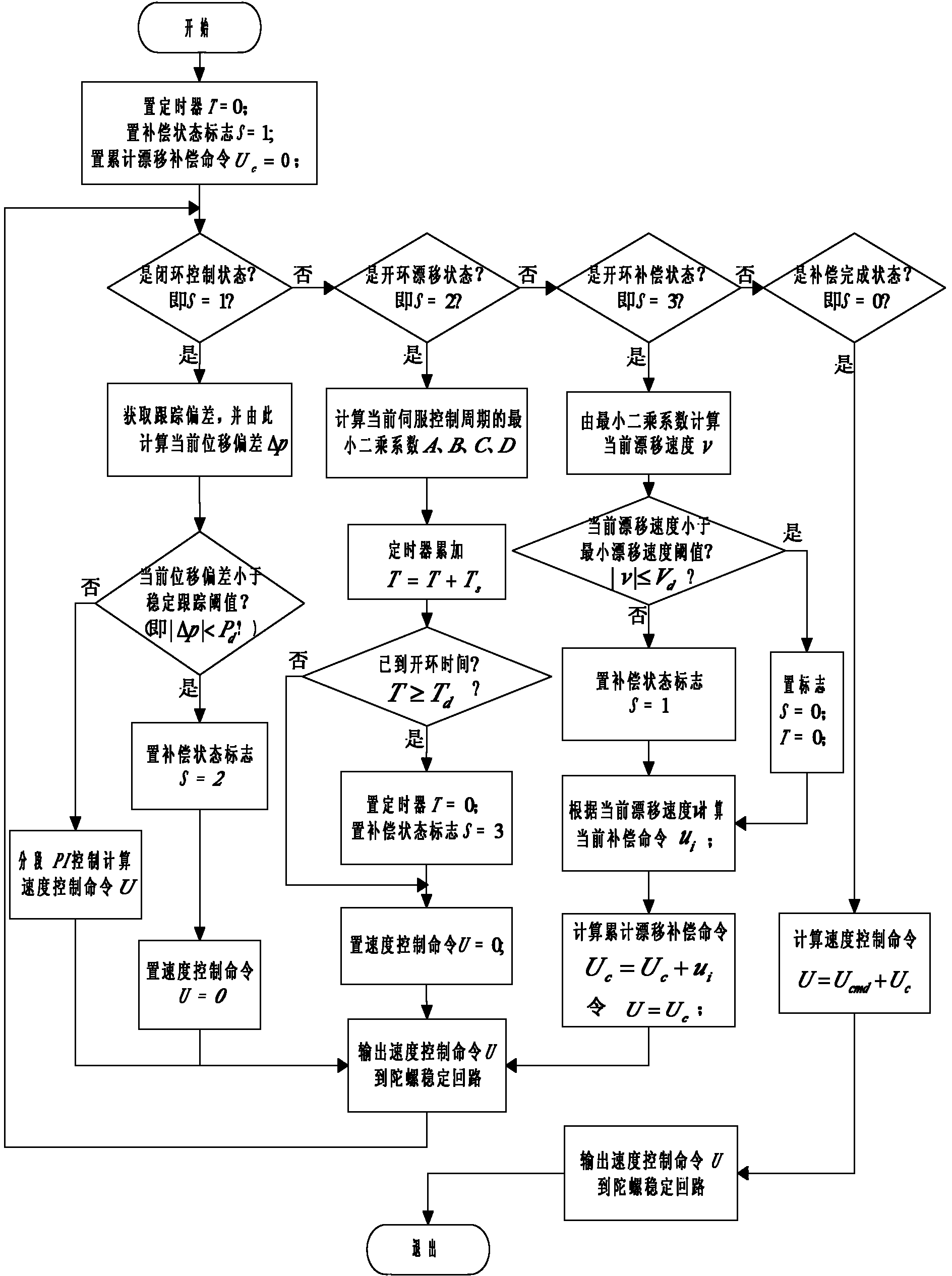
[0032] The preferred embodiment of the present invention is the existing airborne two-axis four-frame photoelectric stabilization system, and the automatic compensation method for the line of sight drift is realized by the drift automatic compensation module built in the servo control computer. Known constants for automatic drift compensation are stored in the static memory of the servo control computer.

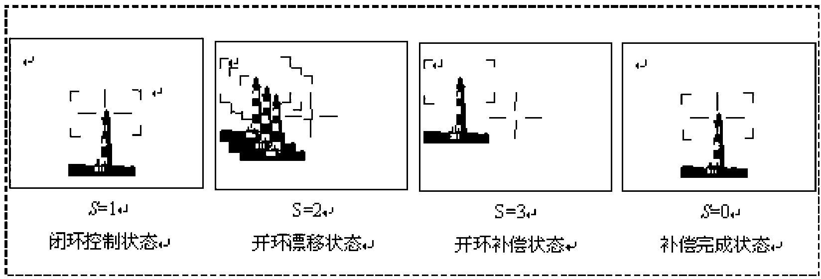
[0033] When it is necessary to perform drift compensation for the photoelectric stabilized sight system, the operator first powers on the system, controls the photoelectric stabilized sight system to align the line of sight at a stationary target, switches the TV sight to a small field of view, and enters the automatic tracking mode. The tracking wave gate traps the target, and the line of sight cross remains at the center of the t...


PUM


Abstract

The invention discloses an automatic compensation method for static drift of a sight line of a stabilized photoelectric sight system, and belongs to the field of automatic control. The method comprises the steps that an automatic tracking control loop is disconnected under a small view field of a sight tool of the stabilized photoelectric sight system; the tracking displacement deviation is counted in a certain period; the drift velocity of the sight line is calculated by using a least square curve fitting algorithm; the drift velocity is converted into corresponding control voltage; a gyro stabilization loop is reversely added to compensate drift motion; and a servo control system is controlled by a timer to automatically and repeatedly execute the operation until the drift velocity is less than a specified threshold. The method is achieved by completely adopting a software algorithm, solves the problems of slow manual drift compensation and low compensation accuracy, is simple in algorithm and high in portability, and is suitable for drift compensation of the sight line of the existing on-board stabilized photoelectric sight system.

Description

technical field [0001] The invention belongs to the field of automatic control, and mainly relates to a line-of-sight drift compensation method of a photoelectric stabilization system, in particular to an automatic compensation method for static line drift of an airborne photoelectric stabilization system. Background technique [0002] The airborne photoelectric stabilization system is a kind of photoelectric equipment installed on the weapon platform to detect, identify and aim at the target. It generally uses the rate gyroscope as the angular velocity sensitive element, and through the closed-loop control of the velocity, it ensures that the line of sight is in the inertial space. of stability. When the photoelectric stabilized aiming system is put into use, with the change of time and temperature, the characteristics of the system components will change to a certain extent, and the static drift of the line of sight will also change accordingly. Therefore, before the airc...

Claims


Application Information

Patent Timeline
IPC IPC(8): G05B13/04
Inventor 吴玉敬李超桑蔚王新伟徐东华雷霏霖张冲张慧刘建伟吴慰赵创社张一军
Owner 西安应用光学研究所
Why Eureka
Try Eureka