
Electricity-generation system and wireless power-transmission system

A power generation system and electric power technology, which is applied in electromagnetic wave systems, photovoltaic power generation, circuits, etc., can solve problems such as increased losses, and achieve the effects of reducing the number of power conversions and effectively distributing power

Inactive Publication Date: 2013-07-31
PANASONIC CORP
View PDF6 Cites 1 Cited by
  • Summary
  • Abstract
  • Description
  • Claims
  • Application Information

AI Technical Summary

Problems solved by technology

Specifically, since the output DC power is temporarily converted to AC power by the power conditioner, and then converted to DC power again in the power distribution system, the loss due to power conversion becomes large

Method used


Image

  • Electricity-generation system and wireless power-transmission system
  • Electricity-generation system and wireless power-transmission system
  • Electricity-generation system and wireless power-transmission system

Examples


Embodiment Construction

[0045] Hereinafter, embodiments of the present invention will be described with reference to the attached drawings. In the following description, the same reference signs are assigned to the same or corresponding elements.

[0046] The power generation system of this embodiment is a solar power generation system used in a detached house. In addition, the power generation system of this embodiment is applicable not only to single-family houses, but also to buildings such as individual households, offices, and buildings of collective housing.

[0047]

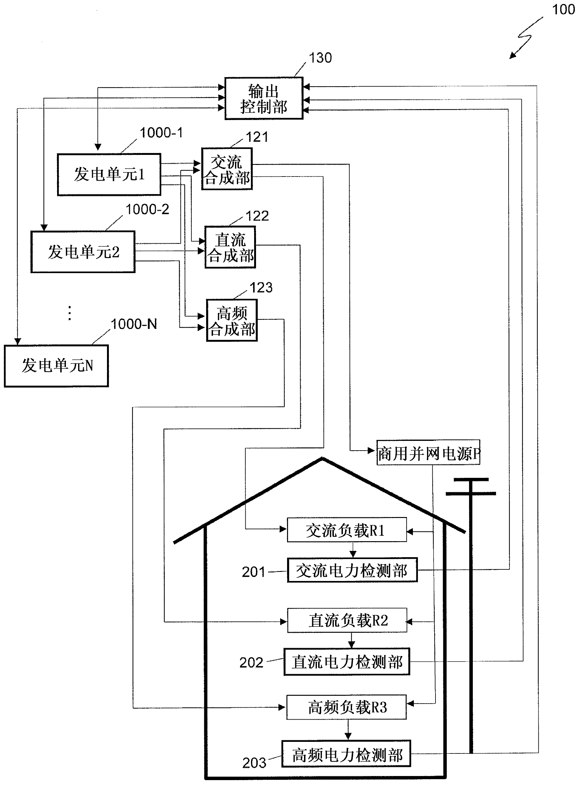
[0048] figure 1 It is a block diagram showing the overall configuration of the power generation system 100 of this embodiment. In addition, in figure 1In the figure, alternating current (AC) load R1, direct current (DC) load R2, high frequency (HF) load R3, and commercial grid-connected power supply (commercial power grid) P that are not components of power generation system 100 are also shown. The AC load R1 represents a...


PUM


Abstract

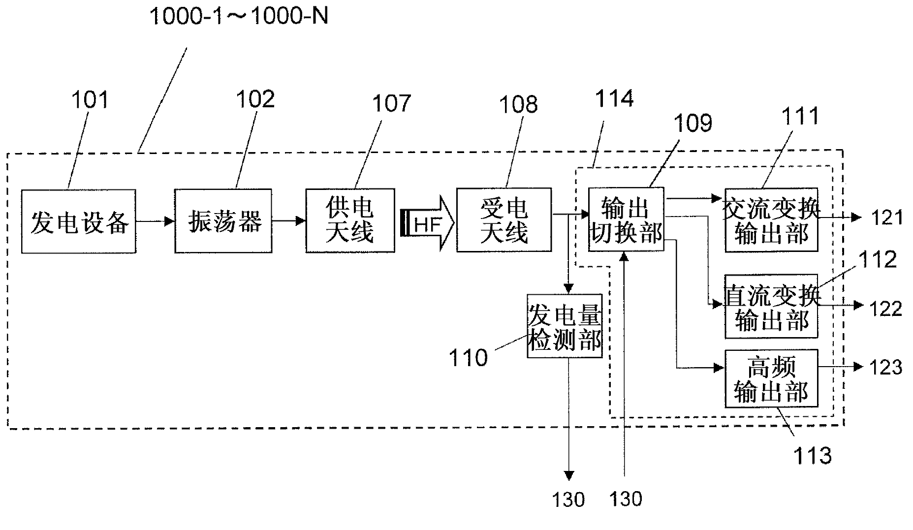
This electricity-generation system is provided with the following: a plurality of electricity-generation units (1000-1 to 1000-N) that wirelessly transmit generated electrical power via magnetic-field coupling between resonators; an AC combining unit (121) that combines AC energy outputted from an AC conversion / output unit in each electricity-generation unit and supplies said AC energy to an AC load; a DC combining unit (122) that combines DC energy outputted from a DC conversion / output unit in each electricity-generation unit and supplies said DC energy to a DC load; and an output control unit (130) that controls the output of each electricity-generation unit by sending control signals to an output switching unit in said electricity-generation unit on the basis of the power consumption of at least one of the AC load and the DC load.

Description

technical field [0001] The present invention relates to a power generation system that efficiently distributes electric power generated by a plurality of power generation units, and a wireless power transmission system. Background technique [0002] Conventionally, a power distribution system for distributing AC power and DC power to loads (electric appliances such as lighting) installed in buildings has been proposed. For example, Patent Document 1 discloses a power distribution system in which not only AC power but also DC power can be supplied by providing a terminal for outputting DC power to an AC power outlet installed on a wall or the like in a room. electricity. This power distribution system includes: a distribution board having a transformer and a rectifier; and an AC power outlet having a DC output terminal. The transformer transforms the 100V or 200V AC voltage into 6V, 3V, 1.5V AC voltage used by the AC load, and outputs it to the rectifier. The rectifier rec...

Claims


Application Information

Patent Timeline
Patent Type & Authority Applications(China)
IPC IPC(8): H02J3/38H02J17/00
CPCH02J4/00H01F38/14H02J5/005H02J3/383H02J1/102H02J17/00Y02E10/563H02J2310/12H02J2300/24H02J3/381Y02E10/56H02M7/05H02J50/80H02J50/23
Inventor 山本浩司菅野浩
Owner PANASONIC CORP
Learn More