Screening device for efficient separation and slagging of mass-flow slurry

A kind of screening equipment and high flow technology, which is applied in the direction of solid separation, filter screen, grid, etc., can solve the problems of high-efficiency screening treatment of slurry that cannot be large flow, hinder the uniform transmission of vibration force, and increase production costs, etc., to achieve Simple structure, improved vibration effect, and easy replacement

Inactive Publication Date: 2013-08-07
淄博正邦知识产权企划有限公司
View PDF0 Cites 5 Cited by
  • Summary
  • Abstract
  • Description
  • Claims
  • Application Information

AI Technical Summary

Problems solved by technology

For the material screening link in the production process, if the screening efficiency can be improved, it will have a great impact on the entire production
However, the current situation is that the screening equipment cannot efficiently screen the large-flow slurry. The main problems are:
The two kinds of stretching phenomena occur frequently, which will cause the screen to be damaged in a short time, thus affecting the screening work
[0005] 2. A large amount of slurry is accumulated on the center of the screen, which hinders the uniform transmission of vibration force, resulting in stronger vibration force as it goes to the edge
Therefore, the slurry falling on the edge of the screen is discharged without being fully screened, which not only reduces the screening effect, but also wastes the slurry.
In addition, the screening equipment in the prior art cannot discharge dry slag, and part of the water in the slurry is lost during the screening process, correspondingly, the production cost is also greatly increased

Method used


Image

  • Screening device for efficient separation and slagging of mass-flow slurry
  • Screening device for efficient separation and slagging of mass-flow slurry
  • Screening device for efficient separation and slagging of mass-flow slurry

Examples


Embodiment Construction

[0034] Below in conjunction with accompanying drawing and embodiment, the present invention will be further described:

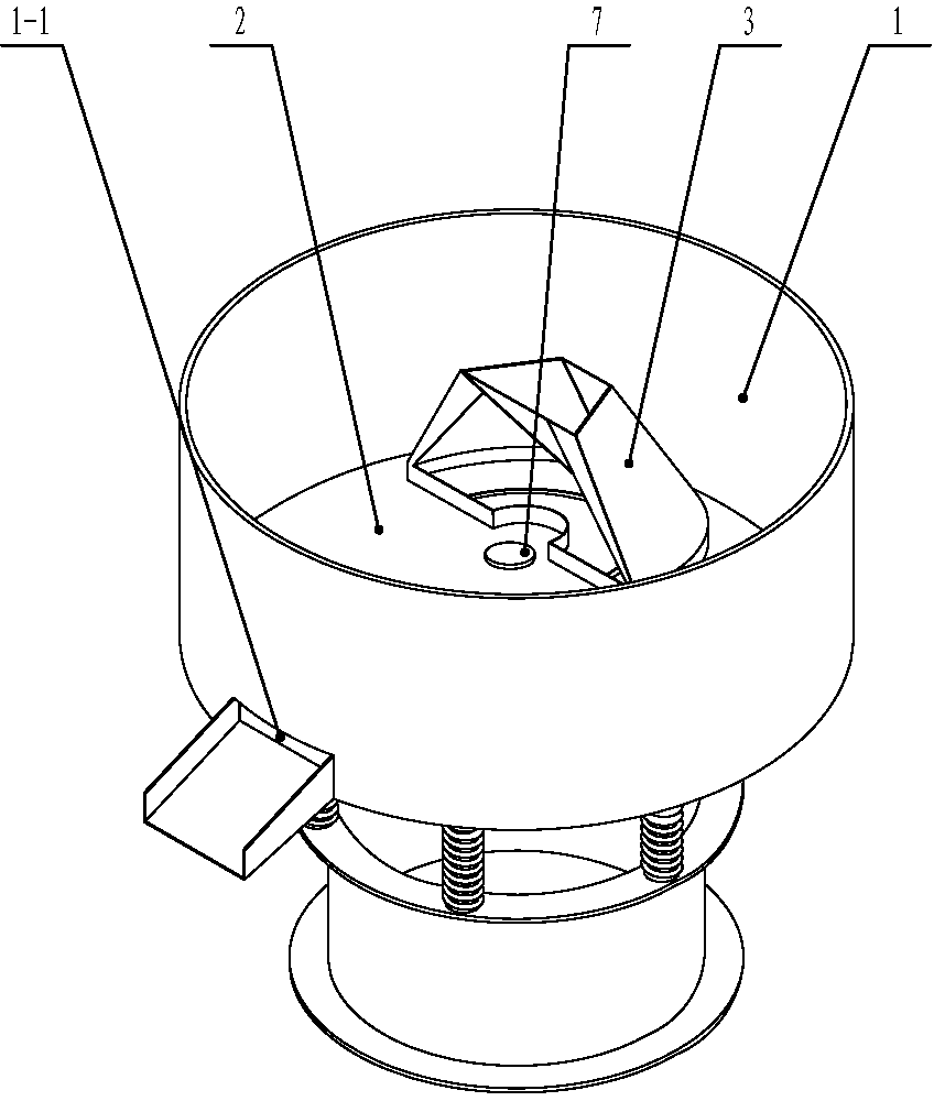
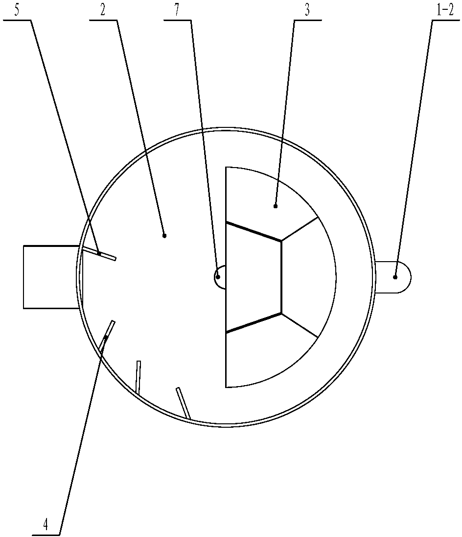
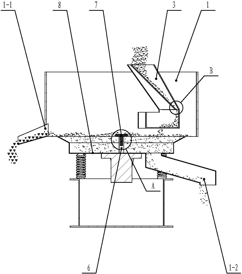
[0035] A screening device for efficiently separating and discharging slag from large-flow slurry is based on a conventional vibrating screen with additional supports, baffles and distributors.

[0036] The specific implementation is as follows: figure 1 and 2 As shown, the equipment includes a vibrating screen frame 8, a screen frame 1 surrounding the screen frame 8, and a screen 2 fixed on the screen frame 1, and the screen frame 1 is also provided with a slag discharge port 1-1. One end of the baffle plate 4 is fixed on the inner wall of the screen frame 1 on both sides of the slag discharge port 1-1 and is located above the screen 2, and the other end faces the slag discharge port 1-1. The bottom edge of the baffle plate 4 contacts or is close to the upper surface of the screen cloth 2 . In order to better improve the screening effect, the length occup...


PUM


Abstract

A screening device for efficient separation and slagging of mass-flow slurry comprises a screen stand, a screen mesh and a screen frame, wherein a slagging port is arranged on the screen frame. The screening device is characterized in that a support body is fixed on the screen stand, and the upper end of the support body is connected with the screen mesh; a material distributor is arranged above the screen mesh, and a gap is reserved between the material distributor and the screen mesh; a hopper and a material distribution plate are connected and arranged in the material distributor, a material discharge port is arranged at the lower end of the hopper, and a material distribution port is arranged on the material distribution plate; a baffle is arranged on the screen frame, one end of the baffle is fixed on the inner wall of the screen frame on the side of the slagging port, the bottom surface of the baffle contacts or is close to the upper surface of the screen mesh, and the other end of the baffle faces to the slagging port. The screening device has the advantages that the middle portion of the screen mesh is fixed through the support body so that the bearing capability of the screen mesh is improved and slurry impact is reduced; and simultaneously the middle portion of the screen mesh cannot fall so that slurry diffuses towards the periphery without gathering at the center, the vibration force is nearly stable, further the vibration effect is greatly improved, and the working state of the screen mesh is greatly improved.

Description

technical field [0001] The invention belongs to the technical field of material screening, and in particular relates to a screening device for efficiently separating and discharging large flow slurry. Background technique [0002] Vibration equipment is widely used in building pottery factories and other enterprises to sort materials. Commonly used vibration equipment includes structural components such as screen frames, screen meshes, springs connected to the screen frames, and vibration motors. The screen is vibrated by starting the vibrating motor, so that the small particles pass through the screen and leak down, and the large particles are blocked on the screen. The screens used in vibration equipment are generally woven with metal wires, nylon wires, etc., and the screens are mostly placed horizontally or with a certain angle of inclination. [0003] In the current industrial production, with the advancement of science and technology, large-scale production is more a...

Claims


Application Information

Patent Timeline
Patent Type & Authority Applications(China)
IPC IPC(8): B07B1/46B07B1/28
Inventor 任祥意
Owner 淄博正邦知识产权企划有限公司
Why Eureka
Try Eureka