Die base on punching machine

A technology of mold library and punching machine, which is applied in the direction of piercing tools, forming tools, manufacturing tools, etc., can solve the problems of enlarged main machine width, high cost investment, and many pipeline layouts, and achieve the reduction of main machine width, debugging and maintenance Convenient and guarantee the effect of nominal pressure

Inactive Publication Date: 2013-08-07
JINAN CASTING FORGING MACHINERY INST
View PDF7 Cites 9 Cited by
  • Summary
  • Abstract
  • Description
  • Claims
  • Application Information

AI Technical Summary

Problems solved by technology

The existence of the eccentric load moment makes the main engine need to provide a mechanism to resist the eccentric load moment. The greater the eccentric load moment, the higher the cost of this mechanism; the length of the mold library will also increase the width of the main engine, making the structural size of the main engine bed Therefore, the weight will be increased, which will directly affect the overall structural performance and the improvement of the operating speed of the host.
The mold change unit adopts the mold selection action that each mold position corresponds to a single-position cylinder. In view of the large number of mold positions, the number of cylinders is large; the piston rod of the cylinder is directly connected with the impact pad, and the cylinder body is seriously damaged. There are many pipeline layouts, cumbersome electrical control, and equipment debugging and maintenance are very difficult; the pressing unit relies on the bed of the punching main machine, and the rotating shaft is often fixed on the main machine bed, and the pressing plate swings and presses the material with the movement of the mold library. In this way, because the binder plate is in a swinging state, it cannot ensure that the binder surface of the binder plate is in contact with the effective surface of the longitudinal beam workpiece surface. During the pressing process, there is a lateral driving force on the longitudi

Method used


Image

  • Die base on punching machine
  • Die base on punching machine
  • Die base on punching machine

Examples


Embodiment Construction

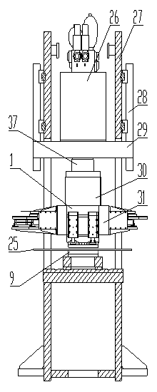
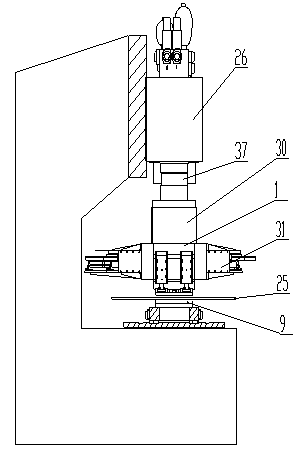
[0015] figure 1 and 2 It is an example of the application of array combined mold library, hydraulic main oil cylinder and main engine bed. figure 1 For assembling the main engine of the hydraulic master cylinder 26 through the main cylinder flange connection plate 29 and the closed bed by the main engine bed connecting plate 28. figure 2 For assembling by the main frame around the facade of the hydraulic main oil cylinder 26 and the open bed.

[0016] figure 1 The upper guide seat 1 of the middle array combined mold library assembly 31 is installed through the mold library connecting slider 30 and the hydraulic main cylinder piston rod 37 of the hydraulic main cylinder 26 installed on the main cylinder flange connection plate 29, which is an array combined type. The mold library component 31 provides the stamping power source; the flange connecting plate 29 of the main oil cylinder is connected with the main machine bed connecting plate 28 installed on the main machine bed...


PUM


Abstract

A die base on a punching machine comprises a punching unit assembly and is characterized in that the punching unit assembly arranges dies in an array combination mode. The dies on the punching unit assembly are distributed towards the periphery with a punching power source as a center and arranged in an array combination mode. A die array is combined freely along a girder feeding direction or along a direction perpendicular to the girder feeding direction. The array combination type die base has the advantage of being compact in structural size, capable of reducing punching slanting bearing pressure, simple and stable in die selecting, good in material pressing effect and the like. By means of an automatic control system, stable punching core guarantee is provided for improvement of performance indexes such as nominal pressure, punching precision, production efficiency of an automobile girder numerical control punching production line.

Description

technical field [0001] This project involves the mold library structure of the punching machine of the CNC punching production line for automobile longitudinal beams. Background technique [0002] The mold library of the punching machine of the automobile longitudinal beam CNC punching production line is equipped with a variety of molds that meet the requirements of the automobile longitudinal beam drilling operation. The mold is automatically selected by the numerical control system, and the punching power source is used to complete the longitudinal beam punching operation. At present, the mold library of the punching machine of the CNC punching production line for automobile longitudinal beams at home and abroad is used as the stamping core, mainly composed of a stamping unit, a mold changing unit and a pressing unit; most of the stamping units adopt single-row die arrangement, double-row die arrangement or single-double The arrangement of molds arranged in combination alo...

Claims


Application Information

Patent Timeline
IPC IPC(8): B21D37/14B21D28/34
Inventor 迟志波赵加蓉
Owner JINAN CASTING FORGING MACHINERY INST
Why Eureka
Try Eureka