Differential laser three-dimensional (3D) metal piece printing method

A technology of 3D printing and metal parts, applied in the field of differentiated laser 3D printing metal parts, it can solve the problems of powder waste, low efficiency and insufficient density of metal parts, so as to ensure the mechanical properties of the surface, improve the molding efficiency, and quickly switch. Effect

Active Publication Date: 2013-08-07
CHANGZHOU TIANZHENG IND DEV CO LTD
View PDF9 Cites 18 Cited by
  • Summary
  • Abstract
  • Description
  • Claims
  • Application Information

AI Technical Summary

Problems solved by technology

In traditional 3D printing, photosensitive resin, nylon, paraffin, paper foil and other organic materials are generally used as the main raw materials. The technology of 3D printing using metal alloy powder is not mature enough. For printing the same metal part, its laser power, laser Parameters such as scanning speed and powder spraying speed are fixed. Therefore, the internal and external mechanical properties of the formed metal parts are almost the same, and some metal parts require higher surface mechanical properties than internal mechanical properties. For metal-like parts, laser parameters that meet the mechanical properties of the metal surface are often used to print the entire metal part, which results in very low forming efficiency of metal parts, and even lower forming efficiency of large metal parts
[0004] In addition, the laser head used in the current laser 3D printing method is only equipped with a powder nozzle, which can meet the printing requirements of general metal parts.
However, for large metal parts and the need to use different metal powders and different powder feeding speeds for 3D printing, this printing method has low efficiency, serious powder waste, and certain defects are prone to exist in the printing process, resulting in insufficient compactness of metal parts.

Method used


Image

  • Differential laser three-dimensional (3D) metal piece printing method
  • Differential laser three-dimensional (3D) metal piece printing method
  • Differential laser three-dimensional (3D) metal piece printing method

Examples


Embodiment 1

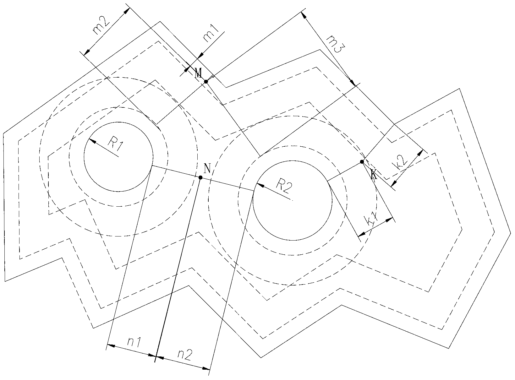
[0037] Such as figure 1 , 2 , 5, and 6, a method for differentiated laser 3D printing metal parts, including:

[0038] A. Pre-divide the area of ​​any point in each layer of printing layer; take any point on the printing layer, the minimum distance from the point to the edge of the printing layer is set as H, and the edge of the printing layer includes the outer edge. If there is hole or cavity, then the edge should also include the inner edge, when 0I+5, this point belongs to the inner 3 of the printing layer, wherein 1<I≤3mm, and the selected value of I is 1mm in the present embodiment;

[0039] B. Place the pretreated printing base and printing base in the printing station, use laser and alloy powder to print metal parts layer by layer on the pretreated printing base, and protect the printing area with inert gas. Nitrogen is generally used, in which, the outer 1 of each printing layer is refined at a low speed, the laser speed is 0.5m / min, the powder feeding speed is 10g / ...

Embodiment 2

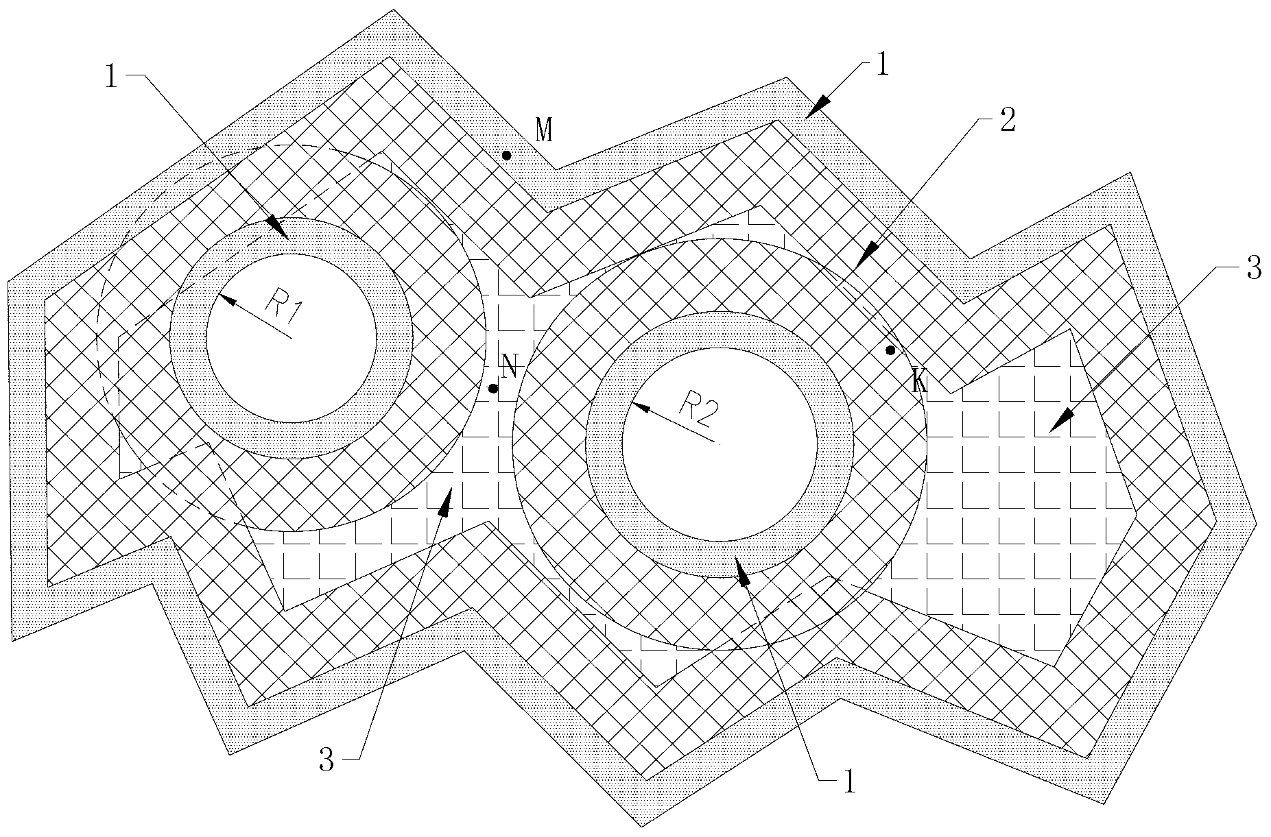
[0048] Such as image 3 As shown, the method of this embodiment is basically the same as that of Embodiment 1, except that the printing layer is slightly different. In the figure, the distance between the inner holes of the metal parts is less than R1+R2+2 (I+I+5) and greater than R1 +R2+2I, wherein, the value of I is 3mm, the same, according to the method in embodiment 1 to image 3 The middle printing layer divides the area, image 3 The figure also schematically shows the inner, middle and outer parts 3, 2 and 1 of the printing layer in three different patterns. The outer 1 of each printing layer is refined at a low speed, the laser speed is 1m / min, the powder feeding speed is 20g / min, and the scanning width is 4mm; the middle of each printing layer 2 is deposited at a medium speed, the laser speed is 3m / min, and the powder feeding The speed is 40g / min, the scanning width is 4mm; the internal 3 high-speed accumulation of each printing layer, the laser speed is 5m / min, the...

Embodiment 3

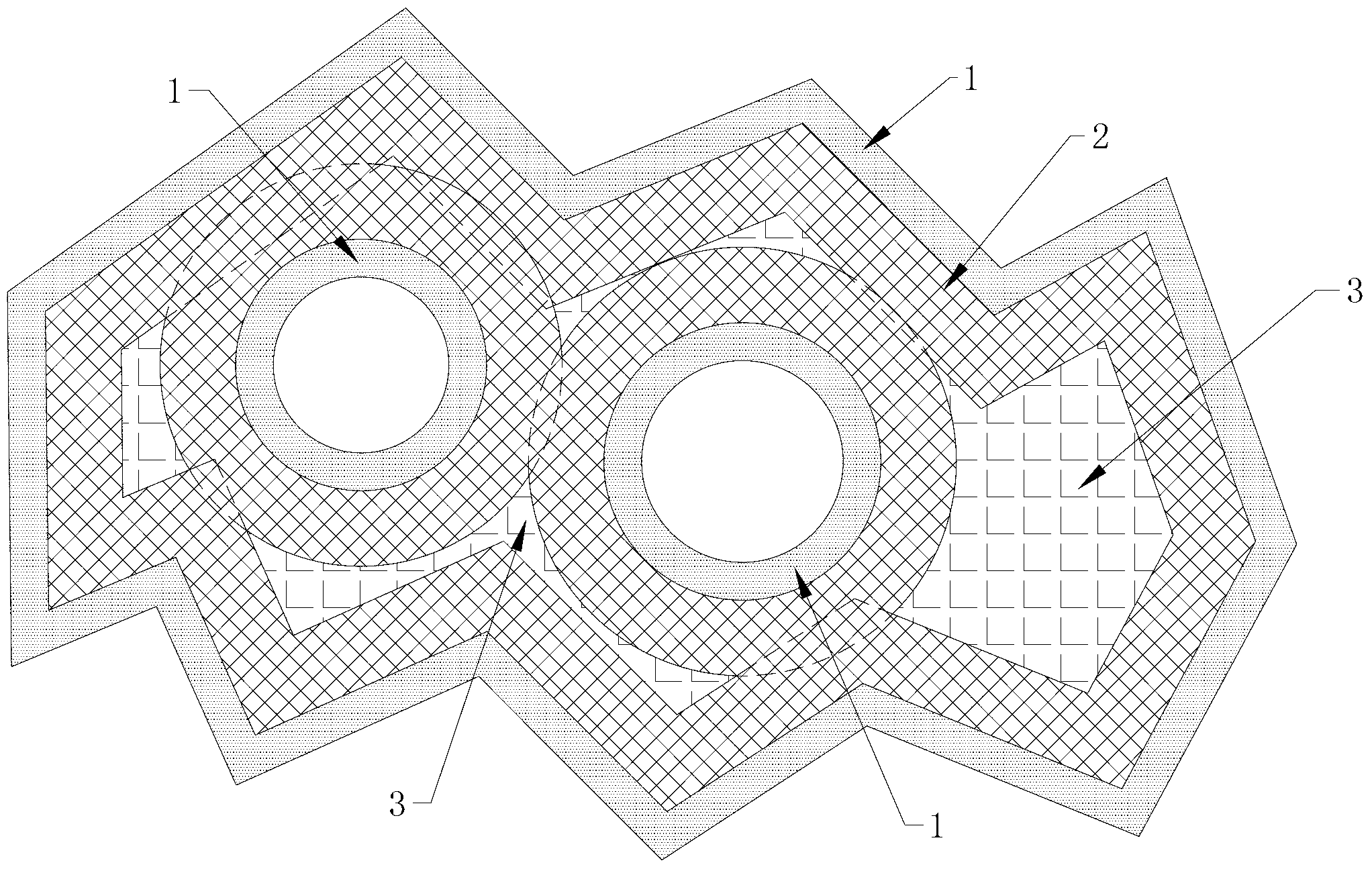
[0055] Such as Figure 4 As shown, the method of this embodiment is basically the same as that of Embodiment 1, except that the shape of the printing layer is slightly different. In the figure, the distance between the inner holes of the metal parts is less than R1+R2+2I, where the value of I is 2mm , similarly, according to the method in Example 1 to Figure 4 The middle printing layer divides the area, Figure 4 The outer 1, middle 2, and inner 3 of the printed layer are also schematically represented in three different patterns. In this embodiment, the outer 1, middle 2, and inner 3 all use fiber lasers. The laser power used in the outer 1 and middle 2 of the printing layer is 2000W, and the laser wavelength is 1.06um; the laser power used in printing the inner 3 is 4000W. The laser wavelength is 1.06um. The outer 1 of each printing layer is refined at a low speed, the laser speed is 0.8m / min, the powder feeding speed is 15g / min, and the scanning width is 2.5mm; the midd...


PUM


Abstract

The invention discloses a differential laser three-dimensional (3D) metal piece printing method. By means of the method, each printing layer is divided into an outer part, a middle part and an inner part, and low-speed fine trimming is conducted on the outer part of each printing layer through laser and alloy powder; intermediate-speed deposition is conducted on the middle part of each printing layer; high-speed accumulation is performed on the inner part of each printing layer, and finally later-stage processing is conducted on the printed metal piece to ensure the boundary dimension to meet the design requirements. By means of the differential laser 3D metal piece printing method, the mechanical requirements of the metal piece can be met, and forming efficiency of the metal piece is greatly improved.

Description

technical field [0001] The invention relates to a method for 3D printing metal parts, in particular to a method for differentiated laser 3D printing metal parts. Background technique [0002] 3D printing technology is an emerging molding method, the core of which is to convert the complex 3D shape of the required workpiece into a combination of simple 2D sections through slicing, so it is not necessary to use traditional processing machine tools and molds. Auxiliary design model, laser 3D printing equipment, under the control of computer, deposits materials layer by layer along the height direction, and makes the layers adhere to each other, and finally accumulates into a three-dimensional workpiece. [0003] At present, the main 3D printing methods include laser curing method, laser sintering method, laser paper cutting method, three-dimensional printing method and melt extrusion method. In traditional 3D printing, photosensitive resin, nylon, paraffin, paper foil and othe...

Claims


Application Information

Patent Timeline
IPC IPC(8): B22F3/105
Inventor 柳岸敏张翀昊杨健邵国峰黄和芳黄佳欣
Owner CHANGZHOU TIANZHENG IND DEV CO LTD
Why Eureka
Try Eureka