Testing device of machine tool spindle dynamics of numerically-controlled machine tool in cutting state

A technology for CNC machine tools and machine tool spindles. It is used in measuring/indicating equipment, metal processing mechanical parts, metal processing equipment, etc. It can solve the problems of error in analysis results, lack of experimental verification, and lack of convincing analysis results, and achieve stability. , to achieve the effect of analysis

Active Publication Date: 2013-08-07
BEIJING UNIV OF TECH
View PDF5 Cites 20 Cited by
  • Summary
  • Abstract
  • Description
  • Claims
  • Application Information

AI Technical Summary

Problems solved by technology

[0004] At present, most of the domestic tests on the dynamic characteristics of the machine tool spindle are carried out in the static state of the machine tool spindle, that is, it is assumed that the dynamic parameters of the machine tool spindle at rest are the same as the actual cutting power parameters of the machine tool spindle, which is obviously more and more unsuitable for high-speed spindles. development needs
In addition, due to the lack of experimental verification of the dynamic characteristics of the machine tool spindle under high-speed operation obtained through numerical analysis, the analysis results obtained are not convincing
The correctness of the numerical analysis depends on the accuracy of the model and boundary conditions, but it is often difficult to accurately model the characteristics of the sliding bearing, hydrostatic bearing and the joint surface between the various parts of the machine tool, so the final analysis results will be very different. big error

Method used


Image

  • Testing device of machine tool spindle dynamics of numerically-controlled machine tool in cutting state
  • Testing device of machine tool spindle dynamics of numerically-controlled machine tool in cutting state
  • Testing device of machine tool spindle dynamics of numerically-controlled machine tool in cutting state

Examples


Embodiment Construction

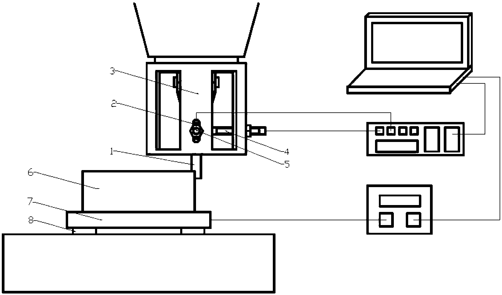
[0026] The following is a further detailed description of the dynamic testing device of the machine tool spindle under the cutting state of the CNC machine tool in combination with the working principle and the drawings of the mechanism.

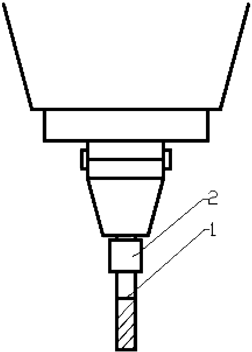
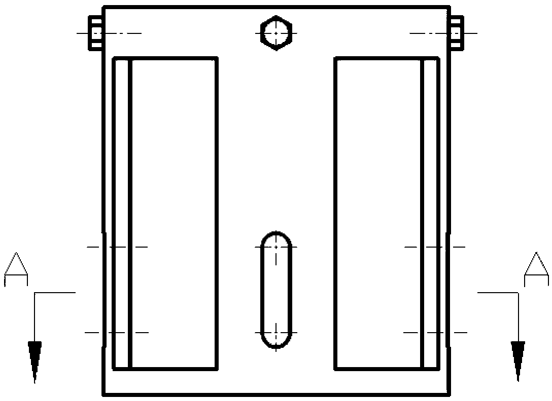
[0027] Such as figure 1 As shown, the middle of the outer surface of the milling cutter sleeve 2 is a smooth test strip with a width of 10 mm and a surface roughness of Ra1.6, and its outer diameter is equal to 5 times the diameter of the test end of the eddy current sensor. The milling cutter sleeve 2 is assembled on the handle of the milling cutter 1 through interference fit, and then the milling cutter 1 equipped with the milling cutter sleeve 2 is installed on the spindle handle of the CNC machine tool, and the milling cutter is measured by a dial gauge to ensure that the milling cutter The radial full run-out of the knife sleeve 2 outer surface smooth test belt is not greater than 0.01mm. The sensor support 3 is a cylindrical device, t...


PUM


Abstract

The invention discloses a testing device of tool spindle dynamics of a numerically-controlled machine tool in a cutting state and belongs to the mechanical vibration and testing field. The testing device of the tool spindle dynamics of the numerically-controlled machine tool in the cutting state comprises the numerically-controlled machine tool, a signal collecting system and an analyzing system. According to the testing device of the tool spindle dynamics of the numerically-controlled machine tool in the cutting state, actual vibration of a machine tool spindle cutting tool is measured through an electrical vortex sensor, an axel center track of the machine tool spindle is drew, cutting stimulus signals the cutting tool actually bear are measured through a cutting force tester, and the test and the analysis of dynamic characteristics of the cutting tool in the actual cutting state are achieved in combination with the measured actual vibration of the cutting tool. The testing device of the tool spindle dynamics of the numerically-controlled machine tool in the cutting state has the advantages of solving the problem that the stability of the machine tool system in the actual cutting state cannot be measured and achieving real-time measure of the numerically-controlled machine tool in the actual cutting state.

Description

technical field [0001] The invention belongs to the field of mechanical vibration and testing, and in particular relates to a dynamic testing device for a machine tool spindle under the cutting state of a numerically controlled machine tool. Background technique [0002] With the rapid development of science and technology, high-performance CNC machine tools continue to develop towards high speed, high precision and high efficiency, and the performance requirements for high-speed spindles are also increasing, especially in the field of high-speed machining, the dynamic characteristics of high-speed spindle processing Has become the core technology of high-speed machining. [0003] In the actual machining process, the dynamic characteristics of the machine tool spindle unit will directly affect the machining accuracy and efficiency. Through the study of the dynamic characteristics of the machine tool spindle, we can find out the weak link of the machine tool structure, and p...

Claims


Application Information

Patent Timeline
Patent Type & Authority Applications(China)
IPC IPC(8): B23Q17/09
Inventor 蔡力钢李根郭铁能赵永胜杨勇
Owner BEIJING UNIV OF TECH
Why Eureka
Try Eureka