
Steel-concrete lapping type combination beam

A technology of concrete and composite beams, applied in the direction of bridges, bridge parts, bridge construction, etc., can solve the problems affecting the stress state and service life of composite beams, long construction period, complex structure, etc., to improve the stress state and service performance, improve Construction efficiency, the effect of simplifying the connection structure

Active Publication Date: 2013-08-07
林同棪国际工程咨询(中国)有限公司
View PDF6 Cites 1 Cited by
  • Summary
  • Abstract
  • Description
  • Claims
  • Application Information

AI Technical Summary

Problems solved by technology

Although such a composite structure lightens the structural weight, the rigid connection makes the steel beam section in the middle of the span deflect along with the shrinkage and creep of the concrete, and bears additional additional loads caused by the creep of the concrete beam section; It obviously affects the stress state and service life of the composite beam; at the same time, the rigid connection structure has various forms, complex structure, and long construction period

Method used


Image

  • Steel-concrete lapping type combination beam
  • Steel-concrete lapping type combination beam
  • Steel-concrete lapping type combination beam

Examples


Embodiment Construction

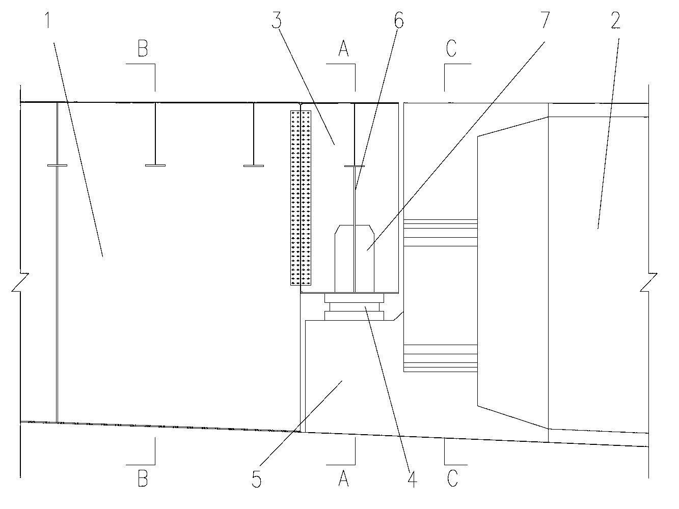
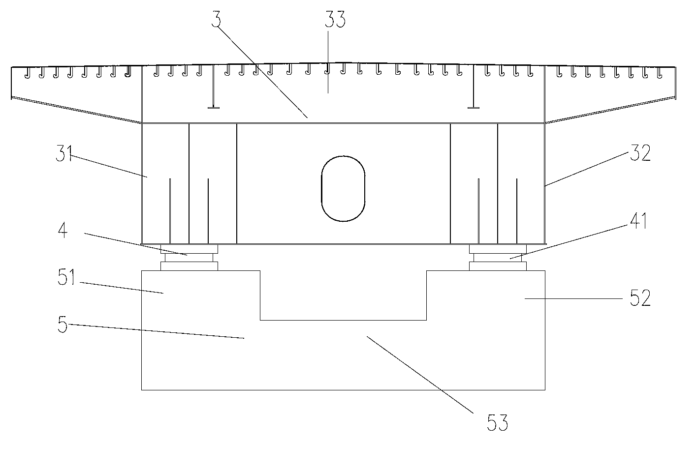
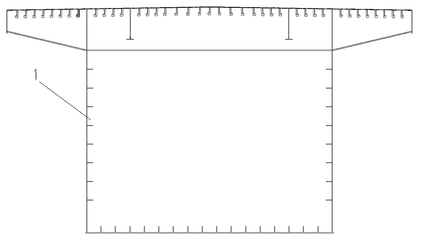
[0018] figure 1 It is a structural schematic diagram of the present invention; figure 2 It is a schematic diagram of the structure of A-A of the present invention; image 3 It is a schematic diagram of the B-B structure of the present invention; Figure 4 It is a schematic diagram of the C-C structure of the present invention; as shown in the figure: a steel-concrete lap composite beam of the present embodiment includes a steel box girder section 1 and a concrete beam section 2 positioned at both ends of the steel box girder section 1. The two ends of the steel box girder section 1 are overlapped with the concrete beam section 2; the overlapping connection structure produces a performance similar to a hinge, so that the freedom of longitudinal rotation between the steel beam section and the concrete beam section can be achieved.

[0019] In this embodiment, the concrete girder section 2 and the steel box girder section 1 form a notch overlapping structure; the longitudinal ...


PUM


Abstract

The invention discloses a steel-concrete lapping type combination beam which comprises a steel box beam section and concrete beam sections located at two ends of the steel box beam section. The two ends of the steel box beam section are connected with the concrete beam sections in a lapping mode, and an incision lapping structure is formed by the concrete beam sections and the steel box beam section. A lapping connection structure is adopted, performances similar to hinge joint are generated so as to enable the steel box beam section and the concrete beam sections to perform longitudinal rotation freedom degree, simultaneously due to the lapping structure, no large restriction exists in the longitudinal direction, and longitudinal relative motion is formed when the concrete beam sections have creep so as to reduce or avoid restriction of the steel box beam section because of the creep of the concrete beam sections. The steel-concrete lapping type combination beam can effectively reduce or avoid cross steel beam section flexibility caused by shrinkage and creep of a long span continuous steel structure, prevents the steel box beam section from bearing additional load caused by the creep of the concrete beam sections, enables stress state and usability to be improved, enables service life to be prolonged, simultaneously can simplify a connecting structure of the steel box beam section and the concrete beam sections, simplifies construction, saves construction cost, and improves construction efficiency.

Description

technical field [0001] The invention relates to a bridge, in particular to a steel-concrete lap joint composite beam. Background technique [0002] Prestressed concrete continuous steel bridges are widely used in the span range of 100m-300m because of their strong spanning capacity, economical appearance and other factors. However, due to the unique shrinkage and creep of concrete, many of these bridges have a continuous increase in mid-span deflection during service, which seriously affects the practical performance of the bridge. In addition, due to the heavy weight of concrete, as the span increases, the prestressed concrete continuous steel bridge is no longer applicable, thus limiting the span of the prestressed concrete continuous steel structure. In order to solve the above problems, a combination beam of steel girder + concrete bridge deck has emerged, that is, a composite beam of steel and concrete is used in different sections of the same beam, and steel structure...

Claims


Application Information

Patent Timeline
Patent Type & Authority Applications(China)
IPC IPC(8): E01D2/04E01D19/00
Inventor 邓文中
Owner 林同棪国际工程咨询(中国)有限公司
Learn More