
Underground optical fiber flow sensor in oil field

A fiber optic flow and sensor technology, applied in the field of petroleum well logging instruments, can solve the problems that cannot meet the environmental requirements of petroleum downhole flow, and achieve the effect of high measurement sensitivity and high measurement accuracy

Active Publication Date: 2015-04-01
BC P INC CHINA NAT PETROLEUM CORP +1
View PDF6 Cites 0 Cited by
  • Summary
  • Abstract
  • Description
  • Claims
  • Application Information

AI Technical Summary

Problems solved by technology

It overcomes the shortcomings that the existing optical fiber sensors cannot meet the environmental requirements of oil well flow measurement

Method used


Image

  • Underground optical fiber flow sensor in oil field
  • Underground optical fiber flow sensor in oil field

Examples


Embodiment Construction

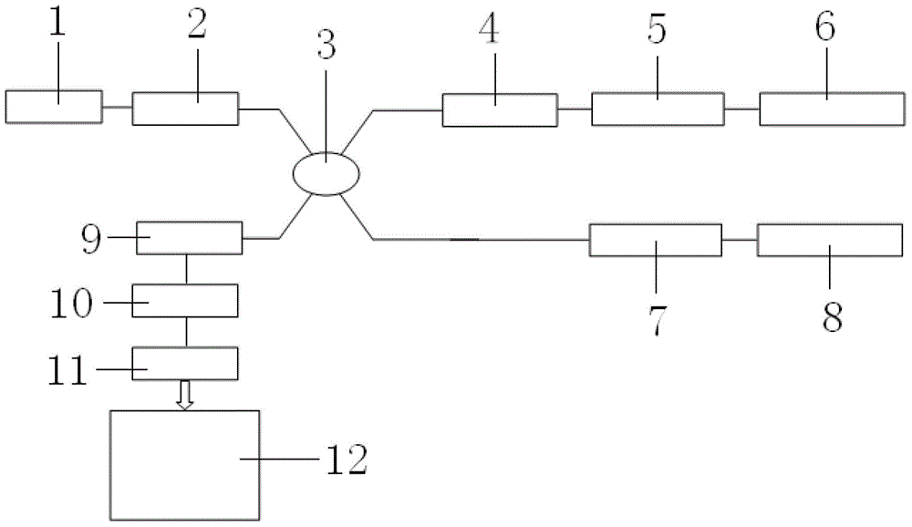
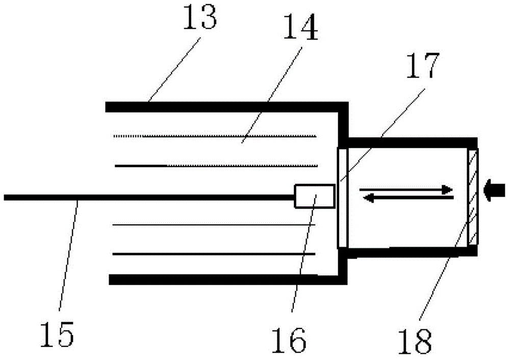
[0012] Such as figure 1 , figure 2 As shown, an oil field downhole optical fiber flow sensor includes a light source module 1; the light source module 1 is connected to a polarization controller 2, the polarization controller 2 is connected to a fiber coupler 3, and the fiber coupler 3 is connected to a phase modulator 4, Faraday rotator Ⅱ7 is connected with photodetector 9, phase modulator 4, Faraday rotator Ⅰ5, optical fiber pressure sensor Ⅰ6 are connected in sequence, Faraday rotator Ⅱ7 is connected with optical fiber pressure sensor Ⅱ8, photodetector 9, magnification The circuit 10, the A / D converter 11, and the embedded computer 12 are connected in sequence. The optical fiber pressure sensitive head I6 and the optical fiber pressure sensitive head II8 have the same structure. The optical fiber pressure sensitive head I6 and the optical fiber pressure sensitive head II8 include a stainless steel shell 13, a stainless steel shell A high-temperature resistant optical fiber ...


PUM


Abstract

The invention relates to a petroleum logging instrument, and particularly to an underground optical fiber flow sensor in an oil field. A light source module of the sensor is connected to a polarization controller; the polarization controller is connected to an optical fiber coupler; the optical fiber coupler is respectively connected to a phase modulator, a Faraday rotating head II and a photoelectric detector; the phase modulator, a Faraday rotating head I and an optical fiber pressure sensing head I are connected sequentially; the Faraday rotating head II is connected to an optical fiber pressure sensing head II; and the photoelectric detector, an amplification circuit and an A / D (Analogue / Digital) converter and an embedded computer are connected sequentially. The underground optical fiber flow sensor in the oil field realizes absence of direct function of a fluid and optical waves, can realizes wholly sealed packaging, satisfies fluid flow measurement in a high-temperature and high-pressure severe environment, has high measurement sensitivity and high measurement precision, and overcomes the disadvantage that the conventional optical fiber sensor cannot be satisfied with the environment requirements of the underground flow measurement of petroleum.

Description

Technical field: [0001] The invention relates to a petroleum logging instrument, in particular to an oil field downhole optical fiber flow sensor. Background technique: [0002] At present, the optical fiber sensors used for liquid flow measurement include turbine optical fiber flow sensors, vortex optical fiber flow sensors, Doppler optical fiber speed sensors, and fiber grating flow sensors. Turbine optical fiber flow sensor has a simple structure and simple signal processing method, but the transmitted light in the optical fiber is projected onto the turbine through the spatial light path, and then the reflected light is received, and the flow measurement is realized by counting. The low flow turbine cannot be started, and the oil The strong absorption of light causes problems such as very weak reflected light, so it cannot meet the requirements of the oil well test environment. The vortex optical fiber flow sensor utilizes the fluid to pass through an obstacle to form two ed...

Claims


Application Information

Patent Timeline
Patent Type & Authority Patents(China)
IPC IPC(8): G01F1/38G01F15/16G01D5/26
Inventor 李天诗汪浩代志勇邬洪亮张胜文江松元毛殿余宫继刚马铭强朱秀英赵俊堂郭洪敏杨留强郑磊陶双福周辉宋菲菲王少鹤李颖李华曹艳玲
Owner BC P INC CHINA NAT PETROLEUM CORP
Learn More