Falling weight impact testing machine

A drop-hammer impact test and heavy-hammer technology, applied in the field of testing machines, can solve the problems of wasting manpower and low work efficiency, and achieve the effects of improving work efficiency, recovering quickly, and preventing secondary impact.

Active Publication Date: 2013-08-07
KUNSHAN INNOVATION TESTING INSTR CO LTD
View PDF5 Cites 17 Cited by
  • Summary
  • Abstract
  • Description
  • Claims
  • Application Information

AI Technical Summary

Problems solved by technology

[0002] The existing drop hammer impact test generally adopts a manual method. Each time, the heavy hammer must be manually hung on the hook, and after the hook is lifted to a certain height, the heavy hammer is free

Method used


Image

  • Falling weight impact testing machine
  • Falling weight impact testing machine
  • Falling weight impact testing machine

Examples


Embodiment 1

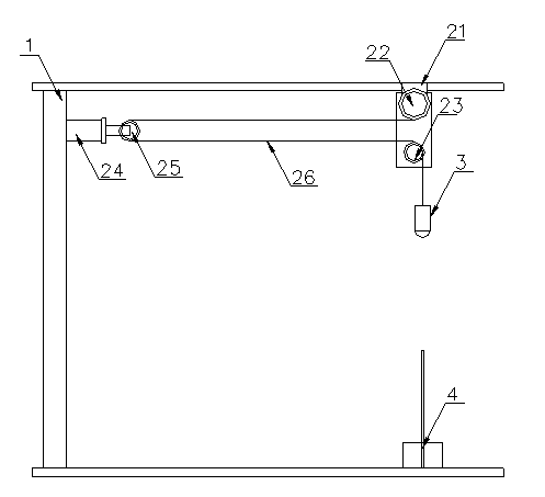
[0024] see figure 1 , as shown in the legend therein, a drop weight impact testing machine comprising:

[0025] a rack 1;

[0026] A lifting mechanism includes a driving motor 21, a cable reel 22, a positioning pulley 23, a high-speed cylinder 24, a movable pulley 25 and a cable 26,

[0027] One impact hammer 3;

[0028] and a loading mechanism 4;

[0029] The positioning pulley 23 is located above the loading mechanism 4;

[0030] The high-speed cylinder 24 is fixed on the frame 1;

[0031] Movable pulley 25 is connected on the piston rod of high-speed cylinder 24;

[0032] The free end of the cable 26 walks around the movable pulley 25 and the positioning pulley 23 successively, and then connects on the impact weight 3 .

[0033] The speed at which the piston rod of the high-speed cylinder 24 releases the cable is greater than the free-fall speed of the impact weight 3 .

[0034] The working principle of the present invention is introduced below.

[0035] Driven by ...

Embodiment 2

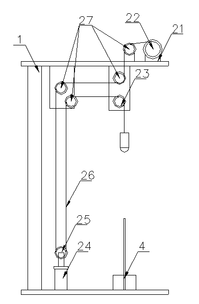
[0037] see figure 2 , as shown in the legend therein, the rest is the same as the embodiment, the difference is that the lifting mechanism also includes four auxiliary pulleys 27,. Adopting this structure makes the structure of the hammer impact testing machine more compact.

Embodiment 3

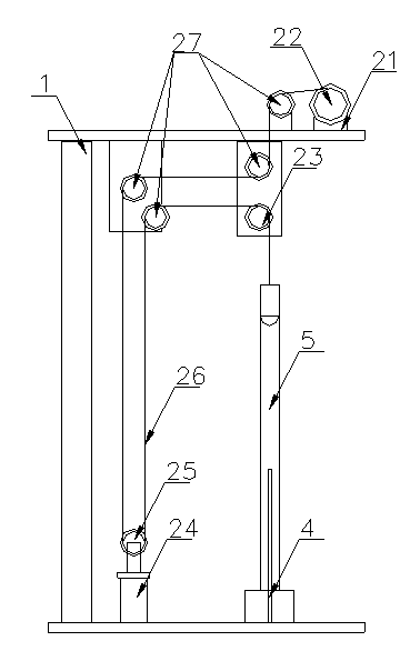
[0039] The rest are the same as in the embodiment 2, the difference is that the drop weight impact testing machine also includes a photoelectric sensor, the photoelectric sensor is arranged at the loading mechanism 4, and when the impact test is completed, the photoelectric sensor senses the corresponding signal , thereby controlling the rapid retraction of the piston rod of the high-speed cylinder 24, so that the impact weight 3 that completes the impact test is rapidly raised, avoiding the secondary impact of the workpiece to be tested.


PUM


Abstract

The invention discloses a falling weight impact testing machine which comprises a rack, a lifting mechanism, an impact counter weight and a load-bearing mechanism, wherein the lifting mechanism comprises a positioning pulley arranged above the load-bearing mechanism and connected with a cable between a cable disc and the impact counter weight, and a cable adjustment mechanism; the cable adjustment mechanism comprises an air cylinder and a movable pulley; the air cylinder is fixed on the rack; and the movable pulley is connected with a piston rod of the air cylinder, and is connected with the cable between the cable disc and the positioning pulley. The falling weight impact testing machine can achieve that a release rate of the cable can be greater than a free falling motion rate of the counter weight, so that a falling weight impact test can be performed without separating the impact counter weight from the cable; the manpower is saved; and the working efficiency is improved.

Description

technical field [0001] The invention relates to a testing machine, in particular to a drop weight impact testing machine. Background technique [0002] The existing drop hammer impact test generally adopts a manual method. Each time, the heavy hammer must be manually hung on the hook, and after the hook is lifted to a certain height, the heavy hammer is free-falling to perform the impact test, and then the operator picks it up. The heavy hammer is hung on the suspension hook again for the next impact test, so repeated, not only wasting manpower, but also low work efficiency. Contents of the invention [0003] The object of the present invention is to provide a drop weight impact testing machine which saves manpower and improves work efficiency. [0004] In order to solve the above problems, the present invention provides a drop weight impact testing machine, comprising: [0005] frame; [0006] The lifting mechanism includes a drive motor, a cable reel and a cable, the...

Claims


Application Information

Patent Timeline
IPC IPC(8): G01N3/303
Inventor 陶泽成
Owner KUNSHAN INNOVATION TESTING INSTR CO LTD
Why Eureka
Try Eureka