Submersible motor rotor broken bar fault recognition method based on HHT (Hilbert-Huang transform)

A technology for submersible motors and rotor broken bars, which is applied in the direction of motor generator testing, etc., and can solve the problems of motor burnout and broken rotor bars that cannot be detected online

Inactive Publication Date: 2013-08-07
HARBIN INST OF TECH
View PDF6 Cites 24 Cited by
  • Summary
  • Abstract
  • Description
  • Claims
  • Application Information

AI Technical Summary

Problems solved by technology

[0003] The purpose of the present invention is to solve the problem that the current broken rotor bar fault of the submersible motor cannot be detected onl

Method used


Image

  • Submersible motor rotor broken bar fault recognition method based on HHT (Hilbert-Huang transform)
  • Submersible motor rotor broken bar fault recognition method based on HHT (Hilbert-Huang transform)
  • Submersible motor rotor broken bar fault recognition method based on HHT (Hilbert-Huang transform)

Examples


specific Embodiment approach 1

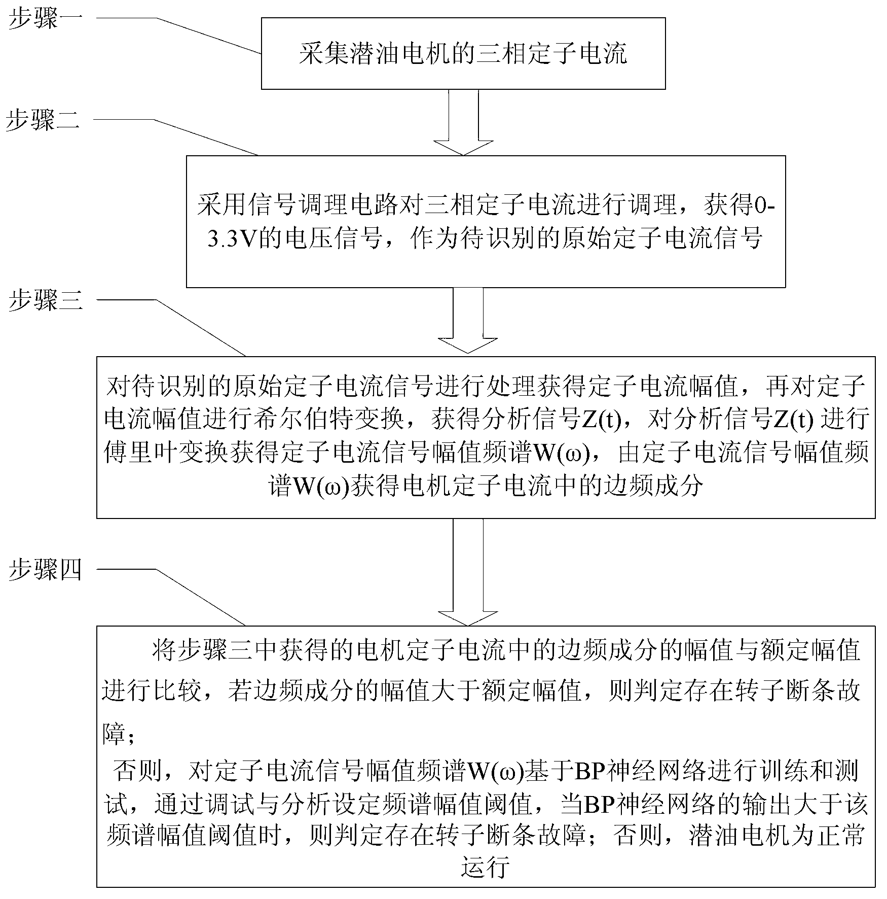
[0051] Specific implementation mode one: the following combination figure 1 Illustrate the present embodiment, the HHT-based submersible motor rotor broken bar fault identification method described in the present embodiment, it comprises the following steps:

[0052] Step 1: collecting the three-phase stator current of the submersible motor;

[0053] Step 2: Use the signal conditioning circuit to condition the three-phase stator current to obtain a voltage signal of 0-3.3V as the original stator current signal to be identified;

[0054] Step 3: Process the original stator current signal to be identified to obtain the stator current amplitude X(t), and then perform Hilbert transformation on the stator current amplitude X(t) to obtain the analysis signal Z(t), and analyze the signal Z(t) is Fourier transformed to obtain the stator current signal amplitude spectrum W(ω), and the side frequency component in the motor stator current is obtained from the stator current signal ampli...

specific Embodiment approach 2

[0061] Specific implementation mode two: this implementation mode further explains the first implementation mode, the amplitude of the side frequency component in the step four is (1-2s)f in the stator current signal amplitude spectrum W(ω) 0 The amplitude at , where s is the slip rate, f 0 is the fundamental frequency in the stator current signal amplitude spectrum W(ω), f 0 = 50Hz.

specific Embodiment approach 3

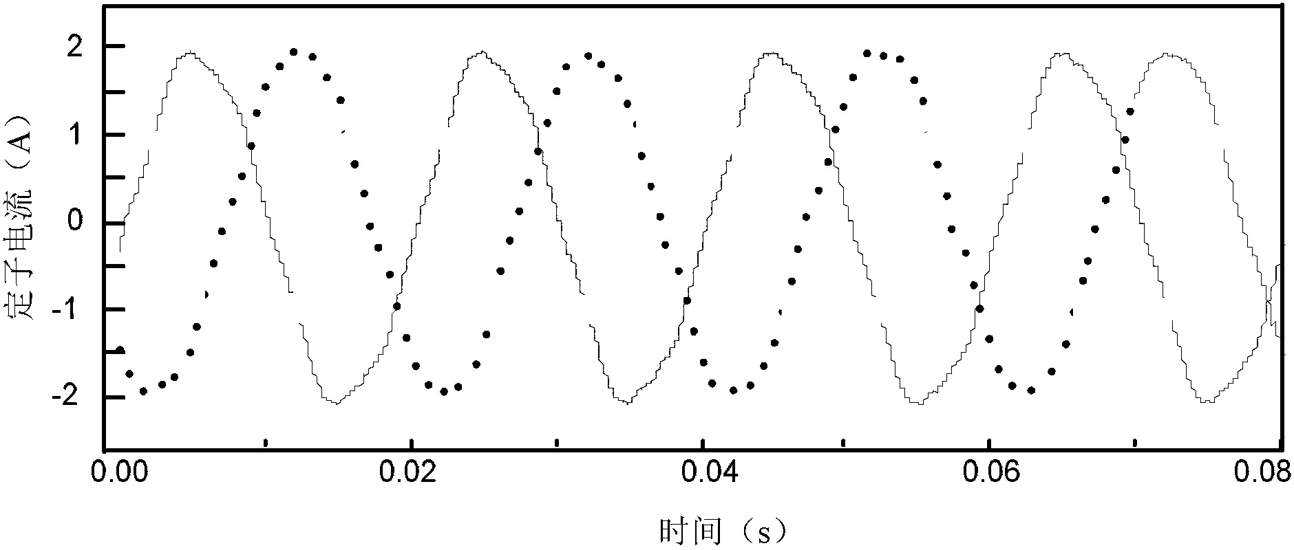
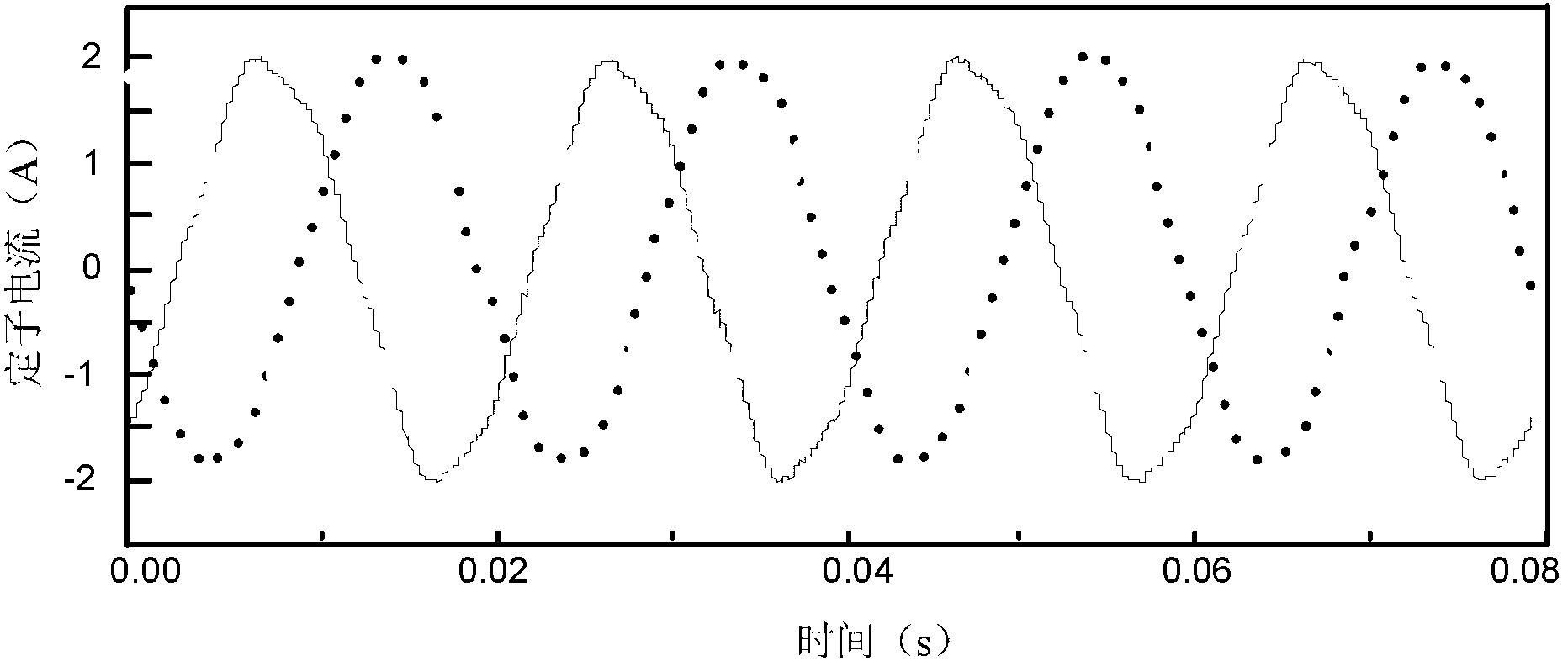
[0062] Specific implementation mode three: the following combination Figure 1 to Figure 11 For illustration, this embodiment will further explain Embodiment 1 or 2. In the step 3, the original stator current signal to be identified is processed to obtain the stator current amplitude X(t), and then the stator current amplitude X(t) Perform Hilbert transform to obtain the analysis signal Z(t), and perform Fourier transform on the analysis signal Z(t) to obtain the stator current signal amplitude spectrum W(ω) The specific process is as follows:

[0063] The original stator current signal to be identified is subjected to empirical mode decomposition until it is screened into the intrinsic mode function, and the intrinsic mode function is used as the stator current amplitude X(t) for Hilbert transformation to obtain the analysis signal Z(t ) The imaginary part Y(t) of the magnitude:

[0064] Y ( t ) = ...


PUM


Abstract

The invention relates to a submersible motor rotor broken bar fault recognition method based on HHT (Hilbert-Huang transform), belongs to the technical field of motor broken bar fault recognition and aims to solve the problem that the rotor broken bar fault of the existing submersible motors cannot be detected online, which causes severe burning loss of the motors. The method includes: acquiring three-phase stator current of a submersible motor; acquiring a 0-3.3V voltage signal as an to-be-recognized original stator current signal, processing to obtain stator current amplitude X(t), acquiring an analyzing signal Z(t), performing Fourier transform to the analyzing signal Z(t) to acquire a stator current signal amplitude frequency spectrum W(omega), and acquiring side frequency component in motor stator current through the stator current signal amplitude frequency spectrum W(omega); and comparing amplitude of the acquired side frequency component with rated amplitude, and judging that rotor broken bar fault occurs when the amplitude of the side frequency component is larger than the rated amplitude. The method is applicable to recognition of submersible motor rotor broken bar fault.

Description

technical field [0001] The invention relates to an HHT-based method for identifying a broken bar fault of a submersible motor rotor, and belongs to the technical field of motor broken bar fault identification. Background technique [0002] Rotor broken bar fault is one of the common faults of submersible motors, and many motor faults related to rotor asymmetry and imbalance are also classified as "generalized rotor broken bar". Due to the initial stage of the broken bar fault, the motor will not have obvious electrical and temperature changes, and the submersible motor generally works in a 2000m deep well, so it is impossible or difficult to directly detect the fault with conventional temperature, pressure, speed and other sensors mutation of the signal. Therefore, when the rotor broken bar fault is serious to a certain extent, it is very likely to cause severe burnout of the motor, which will affect the pump inspection cycle of the oil well and shorten the service life of ...

Claims


Application Information

Patent Timeline
IPC IPC(8): G01R31/34
Inventor 王立国徐殿国侯卓安天琪吴松霖韩宇泽胡东张世博
Owner HARBIN INST OF TECH
Why Eureka
Try Eureka