Automatic teller machine and deflection correcting device thereof

A correction device and deflection correction technology, which is applied in the direction of automatic teller machines, parts of automatic teller machines, deposits in automatic teller machines, etc., can solve problems such as difficulty in meeting the space requirements of deflection correction devices

Active Publication Date: 2013-08-07
GRG BAKING EQUIP CO LTD
View PDF5 Cites 14 Cited by
  • Summary
  • Abstract
  • Description
  • Claims
  • Application Information

AI Technical Summary

Problems solved by technology

[0007] In the case of the compact space structure of the ATM movement, it is difficult to meet the space requirements of the existing deflection correction device

Method used


Image

  • Automatic teller machine and deflection correcting device thereof
  • Automatic teller machine and deflection correcting device thereof
  • Automatic teller machine and deflection correcting device thereof

Examples


Embodiment Construction

[0032] The invention discloses a skew correction device, which reduces the banknote transfer space of the skew correction device; the invention also provides an automatic teller machine.

[0033] The technical solutions in the embodiments of the present invention will be clearly and completely described below in conjunction with the accompanying drawings in the embodiments of the present invention. Obviously, the described embodiments are only some, not all, embodiments of the present invention. Based on the embodiments of the present invention, all other embodiments obtained by persons of ordinary skill in the art without making creative efforts fall within the protection scope of the present invention.

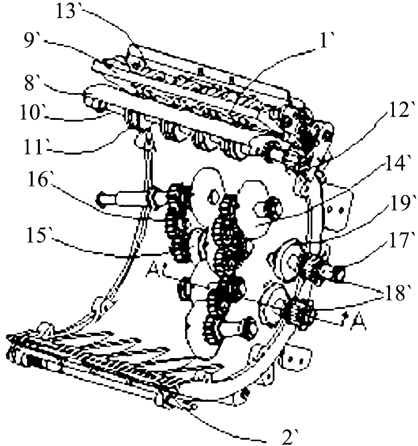
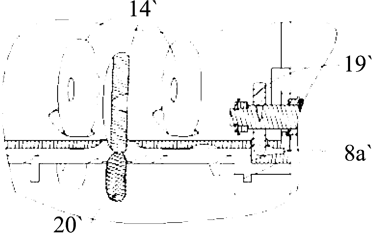
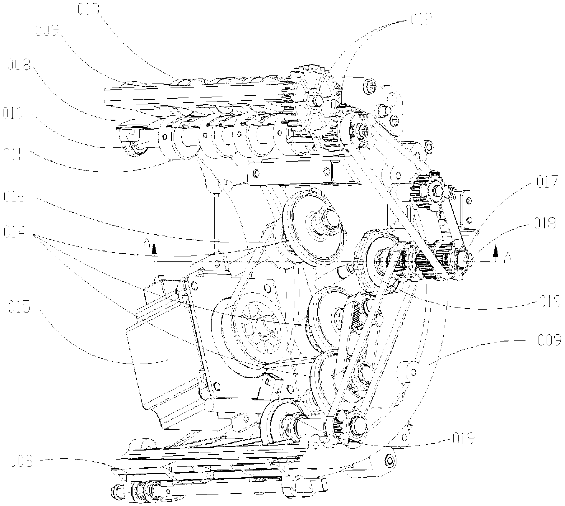
[0034] Such as Figure 3-Figure 7 as shown, image 3 Schematic diagram of the structure of the skew correction device provided by the present invention; Figure 4 for image 3 Schematic diagram of the back structure; Figure 5 for image 3 Schematic diagram of the struc...


PUM


Abstract

The invention provides a deflection correcting device which comprises a bill operation channel composed of a first channel plate and a second channel plate. Bills pass through the bill operation channel and are gradually delivered by a deflection correcting wheel in the bill operation channel to be close to a standard wall. When the bills are close to the standard wall, the bills are delivered into an adjusting wheel. The adjusting wheel and the deflection correcting wheel drive together to deliver the bills, and rotating line speed of the adjusting wheel is larger than rotating line speed of the deflection correcting wheel. Due to the fact that the delivery direction of the deflection correcting wheel is deflected from the standard wall, the front end of the bill delivery direction is close to the standard wall gradually, at this time, the adjusting wheel with higher line speed corrects the bills, the bills are slowly away from the front end of the standard wall, and the tail ends of the bills are gradually close to the standard wall. When the tail ends of the bills are attached to the standard wall, the bills are delivered continuously and set right gradually. Direct guiding of the deflection correcting wheel on the bills is achieved, and a delivery space during correction of the bills is reduced. The invention further provides an automatic teller machine.

Description

technical field [0001] The invention relates to the technical field of automatic teller machines, and more specifically relates to an automatic teller machine and a deflection correction device thereof. Background technique [0002] During the ATM (Automated Teller Machine, automatic teller machine) deposit process, the banknotes put into the deposit slot of the ATM by the customer are often skewed, and it is necessary to correct the skew of the inserted banknotes through the identification module. [0003] Existing deskew devices such as figure 1 with figure 2 as shown, figure 1 It is a schematic structural diagram of a skew correction device provided in the prior art; figure 2 for figure 1 Schematic cross-sectional view of the A-A direction. The deflection correction device is composed of the banknote running channel composed of the arc channel plate (8`), (9`), the correction wheel (14`), the reference wall (8a`) and the multi-deformation adjustment wheel (19`). T...

Claims


Application Information

Patent Timeline
Patent Type & Authority Applications(China)
IPC IPC(8): G07F19/00
CPCB65H5/38B65H9/166B65H2403/20B65H2404/144B65H2404/6111B65H2701/1912G07D11/17G07F19/202G07F19/203B65H20/02B65H23/18B65H2301/3114B65H2301/331B65H2301/3412G07F19/20
Inventor 王鹏李喆
Owner GRG BAKING EQUIP CO LTD
Why Eureka
Try Eureka