
Bridge space radioactive concrete-filled steel tube bridge pier and construction method thereof

A radioactive steel pipe and concrete technology, applied in bridge construction, bridges, bridge parts, etc., can solve the problems of low shear bearing capacity of concrete slabs, poor heat and sound insulation effect, and unclear force on the bottom plate, so as to achieve convenient and efficient construction. , Occupy small urban space, reduce the effect of pipeline relocation

Active Publication Date: 2015-05-20
SHENZHEN BRIDGE DOCTOR DESIGN & RES INSTITUDE CO LTD +1
View PDF6 Cites 0 Cited by
  • Summary
  • Abstract
  • Description
  • Claims
  • Application Information

AI Technical Summary

Problems solved by technology

[0002] Traditional reinforced concrete bridges have the advantages of easy material selection, reasonable use of materials, good durability and fire resistance, low cost, not easy to rust, and low maintenance costs. Disadvantages of poor effect
Reinforced concrete bridge piers take up a lot of urban space in complex and multi-vehicle terrain, and the construction is difficult, the construction period is long, and the spanning capacity is limited
[0003] At present, in the field of bridges, especially in the field of steel truss webs, the trusses and piers are generally separated, and the force is transmitted through the bottom plate in the middle. The problems in this method are as follows: 1. The force on the bottom plate between the truss and the pier is not clear, and the force transmission is complicated , local stress concentration; 2. The shear bearing capacity of the concrete slab between the truss and the pier is small, and the fatigue resistance is poor; 3. The overall stiffness is poor

Method used


Image

  • Bridge space radioactive concrete-filled steel tube bridge pier and construction method thereof
  • Bridge space radioactive concrete-filled steel tube bridge pier and construction method thereof
  • Bridge space radioactive concrete-filled steel tube bridge pier and construction method thereof

Examples


Embodiment Construction

[0029] Below in conjunction with accompanying drawing and specific embodiment, the present invention will be further described:

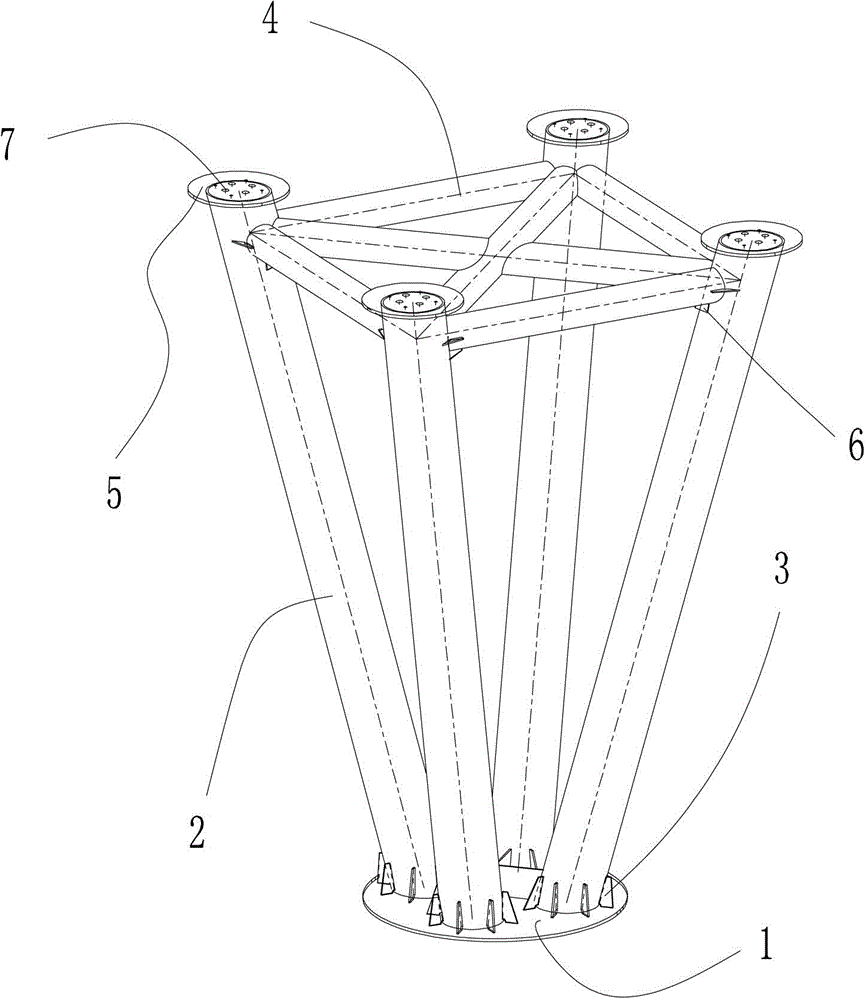
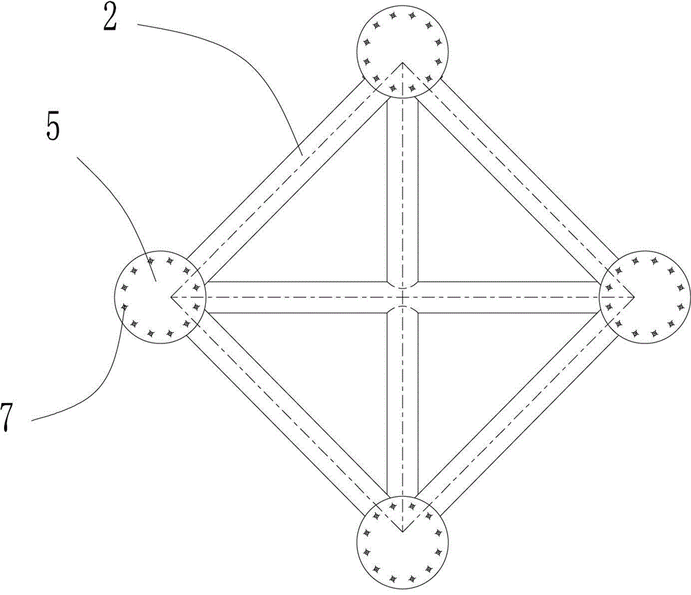
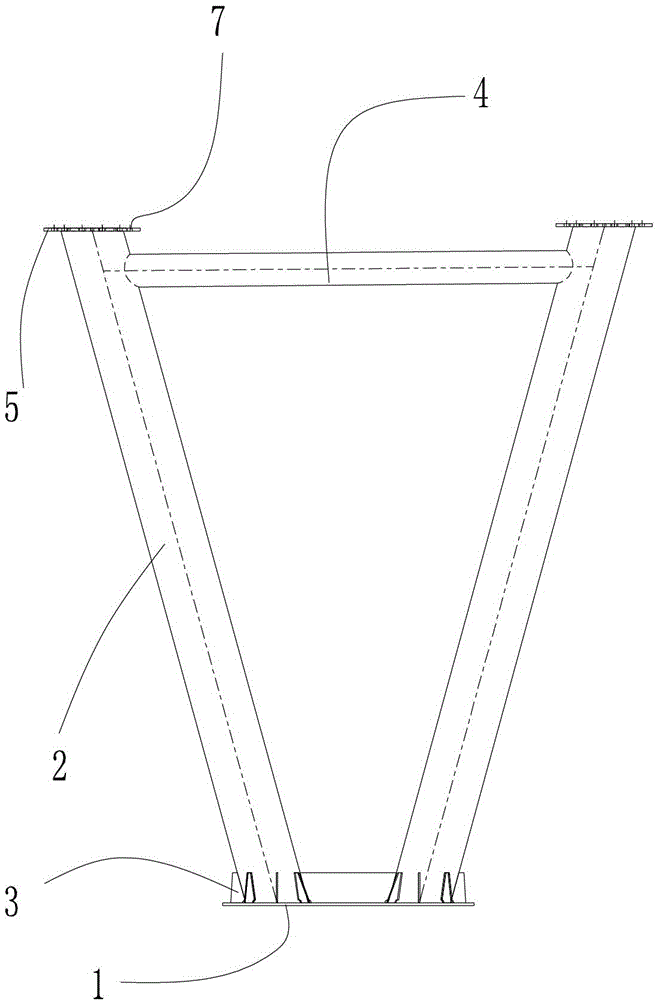
[0030] See Figure 1 to Figure 5 , the present invention relates to a radioactive steel pipe concrete bridge pier in bridge space, and its preferred embodiment includes a flange plate 1, several pier bottom stiffeners 3, four pier support beams 2, six connecting beams 4, four pier top anchor plates 5 and Several contact beam stiffeners6.

[0031] The top surface of the flange 1 is provided with four mounting positions evenly distributed along the circumferential direction.

[0032] The bottom walls of the four pier support beams 2 are respectively installed on the four installation positions on the flange plate 1, and a number of piers evenly arranged in the circumferential direction are welded between the lower end of each pier support beam 2 and the top surface of the flange plate 1 Bottom stiffener 3. The supporting beams 2 of the four piers f...


PUM


Abstract

A bridge space radioactive concrete-filled steel tube bridge pier comprises a flange, a plurality of bridge pier bottom stiffening plates, four bridge pier support beams, six tie beam stiffening plates, four pier top anchor plates and a plurality of tie beam stiffening plates. Four mounting positions in even distribution along the circumferential direction are reserved on the top surface of the flange; bottom walls of the four bridge pier support beams are mounted at the four mounting positions on the flange respectively; a tapered space is formed by encircling of the four bridge pier support beams, and the cross section of the tapered space is decreased gradually from top to bottom; one pier top anchor plate is mounted on the top wall of each bridge pier support beam; and a plurality of anchor bolt preformed holes in even distribution are reserved on each pier top anchor plate. A pile foundation of the bridge pier is centralized blow a bearing platform, and occupied urban space is small. Formwork-free pouring of bridge pier concrete pouring is achieved, and the bridge pier is convenient and efficient to construct, safe and rapid, excellent in structural behavior of rod pieces, higher in rigidity of a main beam, good in stability and the like. The invention further relates to a construction method of the bridge space radioactive concrete-filled steel tube bridge pier.

Description

technical field [0001] The invention relates to a bridge space radioactive steel tube concrete bridge pier and a construction method thereof. Background technique [0002] Traditional reinforced concrete bridges have the advantages of easy material selection, reasonable use of materials, good durability and fire resistance, low cost, not easy to rust, and low maintenance costs. The disadvantage of poor effect. Reinforced concrete bridge piers take up a lot of urban space in complex and multi-vehicle terrain, and are difficult to construct, have a long construction period, and have limited spanning capacity. [0003] At present, in the field of bridges, especially in the field of steel truss webs, the trusses and piers are generally separated, and the force is transmitted through the bottom plate in the middle. The problems in this method are as follows: 1. The force on the bottom plate between the truss and the pier is not clear, and the force transmission is complicated ,...

Claims


Application Information

Patent Timeline
Patent Type & Authority Patents(China)
IPC IPC(8): E01D19/02E01D21/00
Inventor 李勇刘念琴彭跃飞李敏李海史鸣
Owner SHENZHEN BRIDGE DOCTOR DESIGN & RES INSTITUDE CO LTD
Learn More