Supercharge Your Innovation With Domain-Expert AI Agents!

Automatic control device for heating oil tank by using automobile exhaust and automatic control method based on same

An automatic control device and automobile exhaust technology, which is applied in the direction of exhaust device, fuel heat treatment device, noise reduction device, etc., can solve the problems that automatic heating control cannot be realized, and achieve high practical value, wide application space, and high feasibility Effect

Inactive Publication Date: 2013-08-14
HARBIN INST OF TECH
View PDF7 Cites 2 Cited by
  • Summary
  • Abstract
  • Description
  • Claims
  • Application Information

AI Technical Summary

Problems solved by technology

[0017] The purpose of the present invention is to solve the problem that the existing heating device for the fuel tank of diesel vehicles cannot realize the automatic control of the heating process, and provides an automatic control device for heating the fuel tank by using automobile exhaust and an automatic control method based on the device

Method used


Image

  • Automatic control device for heating oil tank by using automobile exhaust and automatic control method based on same
  • Automatic control device for heating oil tank by using automobile exhaust and automatic control method based on same
  • Automatic control device for heating oil tank by using automobile exhaust and automatic control method based on same

Examples


specific Embodiment approach 1

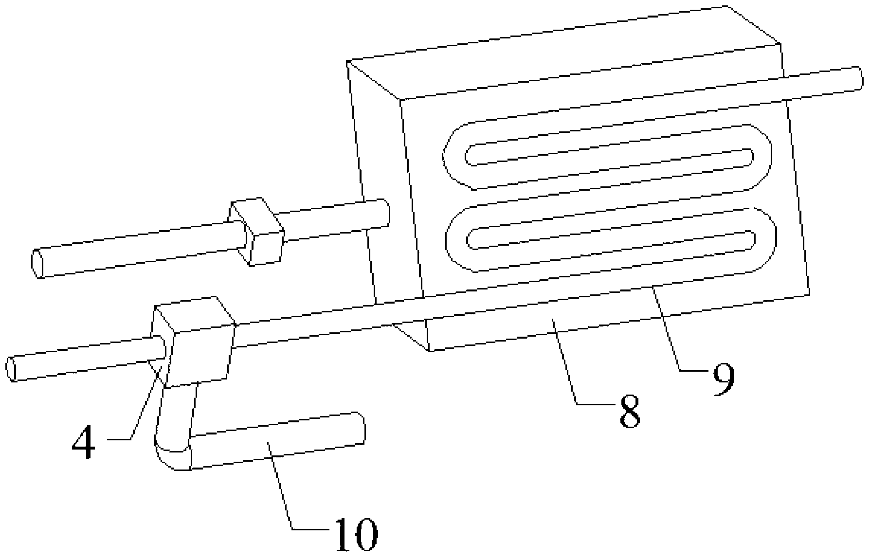
[0035] Specific embodiment one: the following combination figure 1 and figure 2 Illustrating this embodiment, the automatic control device for heating the fuel tank by vehicle exhaust gas described in this embodiment includes an electronically controlled valve 4, a fuel tank 8, a heating pipe 9 and an exhaust gas discharge pipe 10, and the heating pipe 9 is coiled around the bottom of the fuel tank 8, The electronically controlled valve 4 is a three-way structure, one of the three ports of the electronically controlled valve 4 is an automobile exhaust gas inlet, and the other two ports are respectively connected with the air inlet of the heating pipe 9 and the air intake of the exhaust gas discharge pipe 10 . The electric control valve 4 is used to control the communication between the exhaust gas inlet of the automobile and the air inlet of the heating pipe 9, or the communication between the automobile exhaust gas inlet and the exhaust gas discharge pipe 10;

[0036] It al...

specific Embodiment approach 2

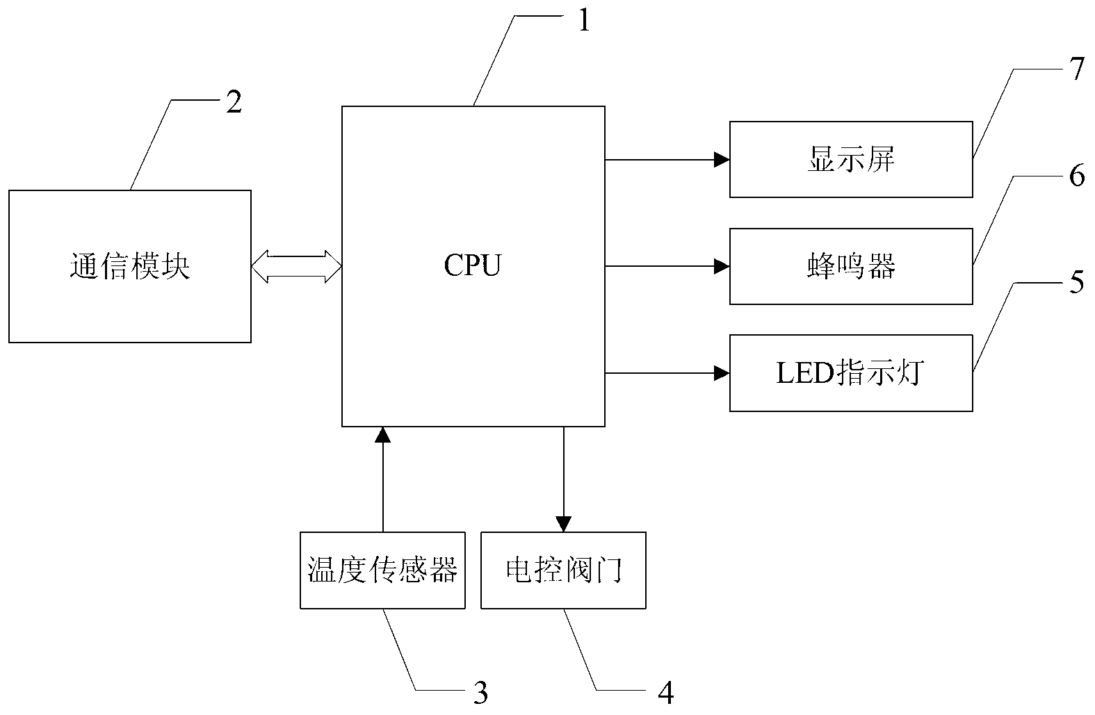
[0040] Specific embodiment two: the following combination figure 2 This embodiment is described. This embodiment further describes the first embodiment. The CPU1 is implemented by a single-chip microcomputer, and the model of the single-chip microcomputer is STC12C5A60S2.

specific Embodiment approach 3

[0041] Specific embodiment three: the following combination figure 2 This embodiment will be described. This embodiment will further describe Embodiment 1. The temperature sensor 3 is implemented by using DS18B20.


PUM


Abstract

The invention relates to an automatic control device for heating an oil tank by using automobile exhaust and an automatic control method based on the same. Through the device and the method, the problem of the existing device for heating a diesel vehicle oil tank can not achieve automatic control of a heating process is solved. The automatic control device comprises an electric control valve, a central processing unit (CPU), a temperature sensor, a light-emitting diode (LED) indicating lamp, a buzzer and a display screen. The automatic control method based on the device includes that the oil tank temperature is detected and displayed; whether the oil tank temperature is larger than or equal to a heating upper limit preset value is judged, on yes judgment, the LED indicating lamp is red, the buzzer alarms, and heating is stopped; whether the oil tank temperature is smaller than or equal to a heating lower limit preset value is judged, on yes judgment, the LED lamp is yellow, and heating is started; and otherwise the LED indicating lamp is green. The automatic control device and the automatic control method are applied to automatic control and heating of the automobile oil tank, especially high-latitude areas and south-north transportation truck groups.

Description

technical field [0001] The invention relates to an automatic control device for heating a fuel tank by using automobile exhaust gas, and an automatic control method based on the device. Background technique [0002] In winter, the temperature drops rapidly. When the diesel temperature is close to or lower than the freezing point temperature corresponding to the diesel grade, the diesel will produce waxing, solidification and other phenomena, thus reducing the fluidity of diesel and affecting the starting and normal operation of diesel vehicles. During operation, the viscosity increases, which affects the atomization effect of diesel and increases fuel consumption. Especially in alpine regions, diesel vehicles may not even work when the situation is severe. Therefore, when winter comes, we can't help but pay attention to the problem of diesel freezing. [0003] In order to prevent diesel oil from waxing at low temperature, the following methods are generally adopted: [00...

Claims


Application Information

Patent Timeline
IPC IPC(8): F01N5/02F02M31/083
CPCY02T10/16Y02T10/12
Inventor 刘永凯胥全春许雲淞于思源周彦平
Owner HARBIN INST OF TECH
Features
  • R&D
  • Intellectual Property
  • Life Sciences
  • Materials
  • Tech Scout
  • Unparalleled Data Quality
  • Higher Quality Content
  • 60% Fewer Hallucinations
Learn More