System and method for gas turbine nox emission improvement

A gas turbine, nitrogen oxide technology, used in gas turbine installations, mechanical equipment, engine control, etc., to solve problems such as inability to comply with emission limits

Inactive Publication Date: 2013-08-14
GENERAL ELECTRIC CO
View PDF7 Cites 7 Cited by
  • Summary
  • Abstract
  • Description
  • Claims
  • Application Information

AI Technical Summary

Problems solved by technology

Gas turbines operating at part load may not be able to comply with emissions limits over the entire part load range (from spinning reserve to near base load)

Method used


Image

  • System and method for gas turbine nox emission improvement

Examples


Embodiment Construction

[0012] Reference will now be made in detail to various embodiments of the invention, one or more examples of which are illustrated in the drawings. Each example is provided by way of explanation of the invention, not limitation of the invention. In fact, those skilled in the art will readily appreciate that various modifications and variations can be made in the present invention without departing from the scope or spirit of the invention. For example, features illustrated or described as part of one embodiment can be used with another embodiment to yield a still further embodiment. Thus, it is intended that the present invention covers such modifications and changes as come within the scope of the appended claims and their equivalents.

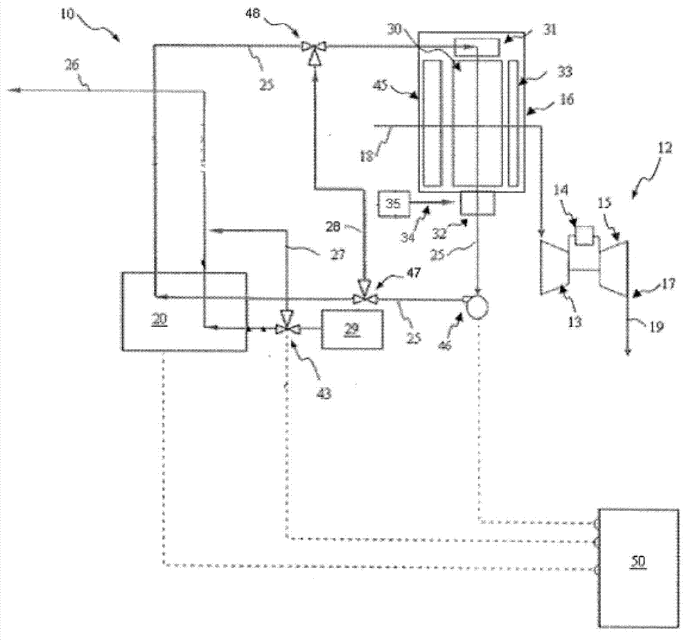
[0013] The present invention is generally directed to systems and methods for improving nitrogen oxide emissions in gas turbines. The systems and methods described in this patent application document reduce nitrogen oxide emissions by heati...


PUM


Abstract

A gas turbine system for NOx emission reduction and part load efficiency improvement is described. The system includes a gas turbine (12) having a compressor (13) which receives inlet-air (18). A direct-contact heat exchanger (30) heats and humidifies the inlet-air (18) before the inlet-air flows to the compressor (13). Heating the inlet-air (18) reduces an output of the gas turbine (12) and extends the turndown range. Humidifying the inlet-air (18) lowers NOx emissions from the gas turbine unit (12).

Description

technical field [0001] The present invention relates generally to gas turbines, and more particularly to methods and apparatus for operating gas turbines. Background technique [0002] Turbines, such as gas turbines, aeroderivative gas turbines, etc., typically operate in combined cycle and / or cogeneration modes. In combined cycle operation, a heat recovery steam generator that produces steam receives exhaust gas from a gas turbine; the steam then flows to a steam turbine that produces additional electricity. In cogeneration operation, a portion of the steam produced by the heat recovery steam generator is sent to a separate process that requires the steam. [0003] Gas turbines are often required to comply with emission limits while generating electricity. Gas turbines operating at part load may not be able to comply with emissions limits over the entire part load range (from spinning reserve to near base load). The turn down range can be considered as the load range ove...

Claims


Application Information

Patent Timeline
Patent Type & Authority Applications(China)
IPC IPC(8): F02C7/08F02C7/00
CPCF05D2270/082F02C3/30Y02E20/16
Inventor 章建民左柏芳B.A.基佩尔
Owner GENERAL ELECTRIC CO
Why Eureka
Try Eureka