
A method, device and system for testing performance of electronic equipment

A technology of electronic equipment and equipment, applied in the electronic field, can solve the problems of consuming designers, consuming a lot of energy, consuming time and cost, and achieving the effect of saving monitoring time

Active Publication Date: 2016-06-22
SHENZHEN SKYWORTH DIGITAL TECH CO LTD
View PDF6 Cites 0 Cited by
  • Summary
  • Abstract
  • Description
  • Claims
  • Application Information

AI Technical Summary

Problems solved by technology

Because in the development stage of electronic equipment, designers need to test under what conditions the electronic equipment will be unstable. However, the instability of electronic equipment cannot be reproduced at the initial stage of design, and the instability is random. If it occurs, the designer does not know under what conditions the instability will occur. Therefore, within the time limit specified for the roasting machine test, the designer needs to spend a lot of energy to monitor the copying test equipment in real time in order to accurately locate the problem.
If the designer ignores the occurrence of unstable conditions during the copy test with a long specified time limit, it will take more time for the designer to perform the copy test again
However, repeating the copying test on the same electronic device will damage the performance of the electronic device. Even the test results obtained by the copying test in the same environment at the same time are random, and the test results obtained by repeated copying tests cannot be determined. The error is within the allowable range, so it not only consumes time and cost, but also cannot accurately locate the problem of unstable electronic equipment, which reduces the efficiency of copying test

Method used

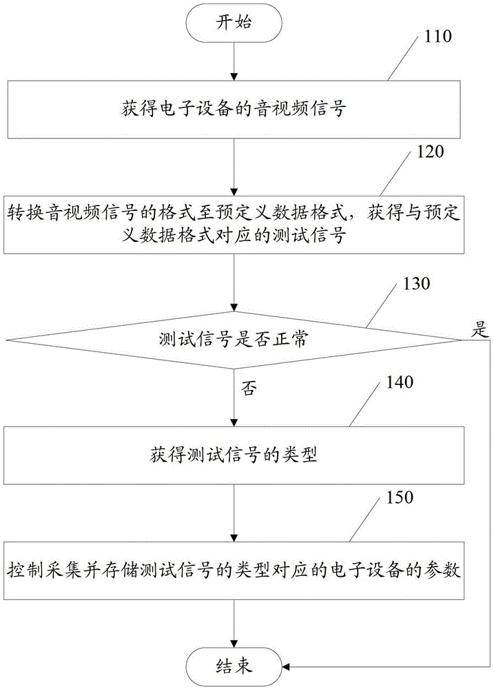
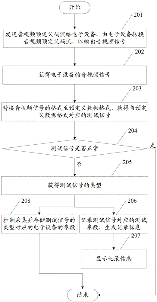
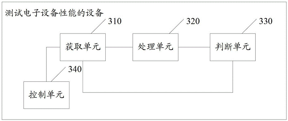

Image

  • A method, device and system for testing performance of electronic equipment
  • A method, device and system for testing performance of electronic equipment
  • A method, device and system for testing performance of electronic equipment

Examples


Embodiment approach

[0116] As an optional implementation, the method also includes:

[0117] Send the preset time range including the current time point to the peripheral parameter acquisition device, and the peripheral parameter acquisition device acquires the parameters of the electronic device corresponding to the type of the test signal within the preset time range.

[0118] As an optional implementation, the type of sending the test signal to the peripheral parameter acquisition device includes:

[0119] Send the test signal to the host computer, so that the host computer sends the type of test signal to the peripheral parameter acquisition device.

[0120] In this embodiment, by sending a test signal to the upper computer, the upper computer controls the peripheral parameter acquisition device to collect the parameters of the electronic device, and the upper computer can be used to realize the diversified collection and control of the parameters of the electronic device, so as to meet diffe...


PUM


Abstract

The embodiment of the invention discloses a method and equipment for testing performances of electronic equipment. The method comprises the steps as follows: obtaining audio and video signals of the electronic equipment; converting the audio and video signal format to a predefined data format, and obtaining a test signal corresponding to the predefined data format; and obtaining the type of the test signal if the test signal is identified to be abnormal, and controlling, collecting and storing parameters of the electronic equipment corresponding to the type of the test signal, so that automatic test on roasting performance of the electronic equipment is realized, monitoring time of test personnel is saved, and collection equipment for collecting parameters of the electronic equipment corresponding to the type of the test signal can be controlled automatically; all required parameters when failure occurs are recorded, so that test personnel can view the parameters of the electronic equipment freely and conveniently; and an auxiliary tool for analyzing failure of the electronic equipment is provided, so that efficiency and accuracy for machine roasting test are further improved.

Description

technical field [0001] The invention relates to the field of electronic technology, in particular to a method, device and system for testing the performance of electronic equipment. Background technique [0002] When existing electronic equipment equipped with audio and video processing devices (such as a set-top box) is in the development stage, designers will conduct reliability tests on the electronic equipment to test the reliability of the electronic equipment. A key link in the reliability test of electronic equipment is the oven test, which refers to the copy machine test after the functional test of the electronic equipment is completed. The oven test is generally divided into low temperature oven test, normal temperature oven test and high temperature oven test. Test, that is, after the functional test is passed, it has been confirmed that the electronic device has no functional problems, then the electronic device is turned on, and then the electronic device is pla...

Claims


Application Information

Patent Timeline
Patent Type & Authority Patents(China)
IPC IPC(8): G01R31/00
Inventor 蒋万辉
Owner SHENZHEN SKYWORTH DIGITAL TECH CO LTD
Learn More