Charging device for electric automobiles

A charging device and technology for electric vehicles, applied in the fields of electric vehicles and vehicles, can solve the problems of delayed charging users, damage to rechargeable batteries, and excessive expenses for vehicle owners.

Inactive Publication Date: 2013-08-14
益阳市海明电子科技有限公司
View PDF11 Cites 5 Cited by
  • Summary
  • Abstract
  • Description
  • Claims
  • Application Information

AI Technical Summary

Problems solved by technology

In this way, the charging will stop before the battery is fully charged, or the charging action will still be invalid when the battery is fully charged, which will invisibly cost the car owner unnecessary costs and cause damage to the rechargeable battery.
In addition, when the battery of an electric vehicle ages after being used for a period of time, it cannot be fully charged or cannot be charged during charging. At this time, the occupation time of the charging socket is also virtually extended, delaying the next charging user.

Method used


Image

  • Charging device for electric automobiles
  • Charging device for electric automobiles
  • Charging device for electric automobiles

Examples


Embodiment 1

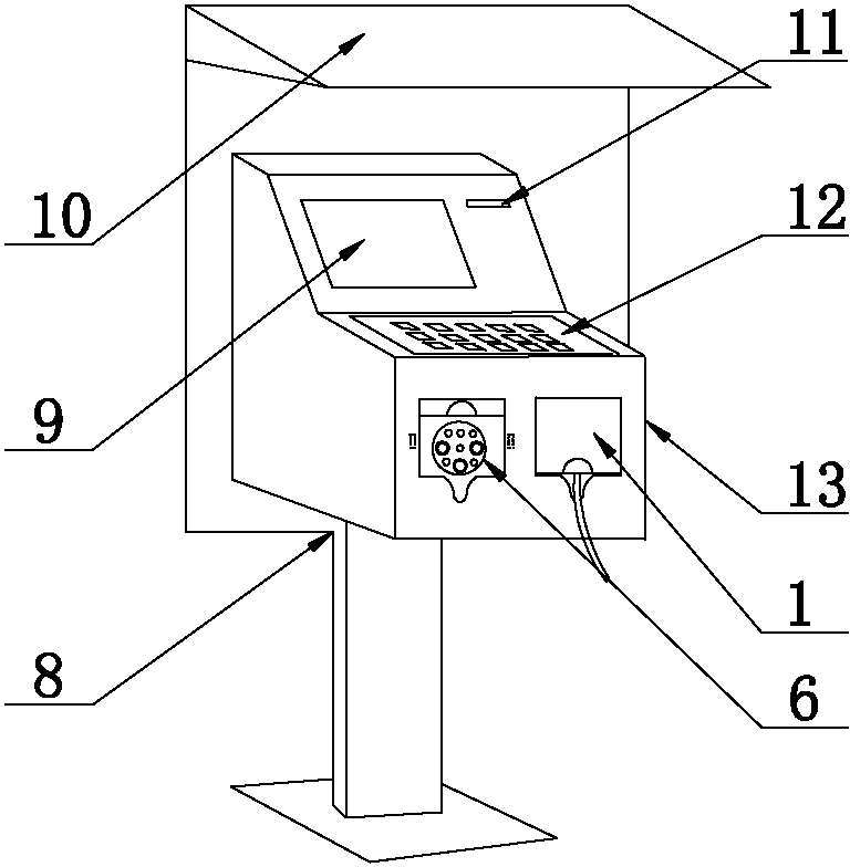
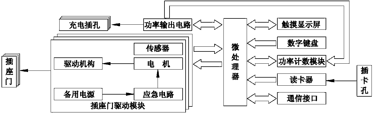
[0027] Depend on figure 1 , figure 2 , image 3 , Figure 4 It can be seen that a charging device for an electric vehicle comprises a main body casing 13 arranged on a fixed frame 8, and the main casing 13 is provided with a touch display screen 9, a numeric keypad 12, a card insertion hole 11, and at least one charging jack 6. The socket door 1 that can close the charging jack 6, the host casing 13 is provided with a card reader connected to the card insertion hole 11, a microprocessor connected to the card reader, the touch display screen 9, and the numeric keypad 12 The main control unit, the microprocessor is connected to the charging jack 6 through the power output circuit; the microprocessor is connected to the corresponding socket door 1 through each socket door drive module to control the opening or closing of each socket door 1.

[0028] In order to save charging time and charging cost in the present invention, the main control unit includes a power counting modul...

Embodiment 2

[0040] Depend on figure 2 , Figure 5 It can be seen that, in order to improve the utilization rate and reduce the occupied area at the same time, the main machine casing 13 is connected with at least one charging socket 14 through the communication cable 7, and the charging socket 14 is provided with a charging socket 6, which can be closed for charging. The socket door 1 of the jack 6; each charging socket 14 is provided with a socket door drive module that controls the corresponding socket door 1 to open or close.

[0041] When the present invention is in use, the user of each charging socket 14 selects the corresponding charging socket 14 on the touch display screen 9 of the same host to operate, and the control command sent by the host microprocessor is transmitted to the charging socket to be used through the communication cable 7 14 socket door driver module.

[0042] The rest are the same as embodiment 1.

Embodiment 3

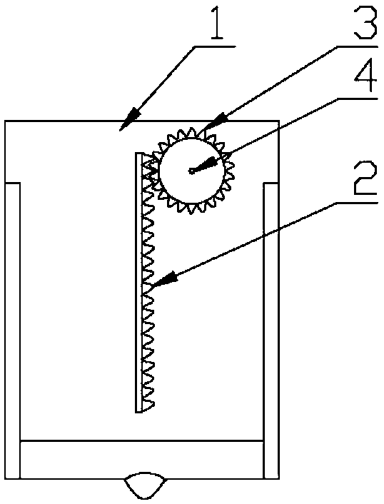
[0044] Depend on figure 2 , Figure 5 , Figure 6 , Figure 7 It can be seen that the driving mechanism of the present invention includes a motor 5 arranged on the main machine casing 13, a gear 3 driven by the output shaft 4 of the motor 5 (the output shaft 4 of this embodiment is parallel to the socket door 1), and a gear 3 arranged on the socket door. 1 on the rack 2 meshed with the gear 3 (the teeth of the rack 2 in this embodiment are perpendicular to the socket door 1).

[0045] Remaining with embodiment 2.


PUM


Abstract

The invention discloses a charging device for an electric automobiles, which is not required to be watched during a charging course and calculates fees according to practical charging quantities. The charging device comprises a host housing (13) arranged on a fixing frame (8), and is characterized in that a touch display screen (9), a numeric keyboard (12), a card slot (11), at least one charging plughole (6) and socket doors (1) of the sealable charging plugholes (6) are arranged on and formed in the host housing (13); a master control unit comprising a card reader connected with the card slot (11), and a microprocessor connected with the card reader, the touch display screen (9) and the numeric keyboard (12) is arranged in the host housing (13); and the microprocessor is connected with the charging plugholes (6) by a power output circuit, and connected with the corresponding socket doors (1) by socket door driving modules. The charging device adopts alternating current for charging, so that the lives of batteries are prolonged; vicious plug removal during the charging course is prevented effectively; the fees are calculated according to the practical charging quantities; multiple automobiles share one charging pile; and the charging device can be widely applied to outdoor environments.

Description

technical field [0001] The invention relates to a vehicle, in particular to an electric vehicle, in particular to a charging device for the electric vehicle. Background technique [0002] With the deepening of the global energy crisis, the increasing thirst of oil resources and the increasing harm of air pollution and global temperature rise, governments and automobile companies in various countries generally recognize that energy saving and emission reduction are the future development direction of automobile technology, and the development of electric vehicles will be The best way to solve these two problems. Electric vehicles are environmentally friendly and represent the future development direction of the automotive industry. At present, the power battery is used as the power source of the electric vehicle to provide power for the vehicle, so that the maximum mileage of the electric vehicle on a single charge is 200 ㎞, but when the power of the power battery is exhaust...

Claims


Application Information

Patent Timeline
Patent Type & Authority Applications(China)
IPC IPC(8): G07F17/00
CPCY02T90/168Y04S30/12Y02T90/167
Inventor 曾晋阶付笑蝉付云蛟刘意诚包浩雷
Owner 益阳市海明电子科技有限公司
Why Eureka
Try Eureka